Overview
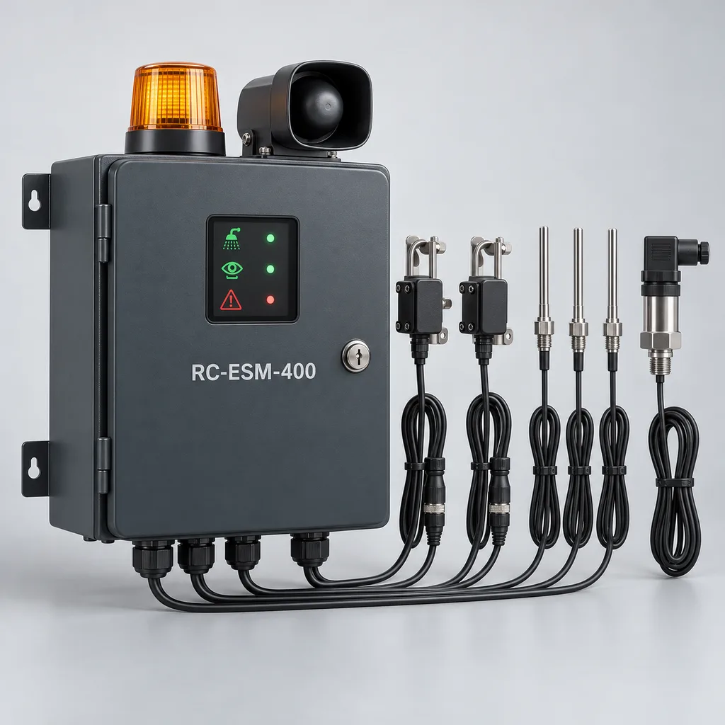
The RC-ESM-400 is a grid-powered emergency safety shower and eyewash monitoring system for industrial campuses, water treatment facilities, maintenance compounds, and outdoor process support areas. It helps safety teams identify station use, receive local and remote alarms, observe water conditions, and maintain inspection records across distributed assets. REDCOAST.LTD supplies the monitoring hardware, Web management platform, mobile App, and project integration as one configurable package, supported by in-house PCB and board-level engineering. The system monitors independently operated emergency fixtures; its electronics never authorize, interrupt, or time-limit emergency water delivery.
Key Features
- Separate shower and eyewash activation detection: Two independent valve-position inputs identify which fixture is being used, including low-flow eyewash operation that a shared high-threshold flow switch could miss.
- Local response without an internet connection: A hardwired activation path operates the station beacon and sounder while the edge controller records the event and forwards it to configured recipients.
- Water-condition visibility: Three temperature channels and optional branch flow transmitters reveal abnormal supply conditions, with inlet pressure monitoring to support maintenance diagnosis.
- Actionable status distinctions: The dashboard separates fixture activation, measured flow, sensor fault, stale data, and overdue inspection. A valve-open signal is never presented as proof of adequate flushing performance.
- Traceable inspection workflows: QR asset identification, technician checklists, measured readings, photographs, and time-stamped acknowledgments replace disconnected inspection spreadsheets.
- Existing-plant connectivity: Ethernet, optional LTE, isolated RS-485, and dry-contact outputs connect stations to the platform or a facility monitoring system.
- Maintainable custom electronics: Replaceable signal-conditioning, isolated I/O, and power-management boards allow project-specific sensor interfaces without replacing the complete station.
- Practical retrofit packaging: A compact outdoor cabinet mounts beside existing fixtures, with a matched sensor harness and optional pedestal for locations without a suitable wall.
Technical Architecture
Each terminal serves one combination shower and eyewash station, or one shower plus one nearby eyewash. The base package includes the controller cabinet, two activation sensors, three temperature probes, one inlet-pressure transmitter, a beacon/sounder assembly, and platform provisioning. Optional flow transmitters use separate measurement ranges for the shower and eyewash branches. REDCOAST.LTD develops the main controller PCB, RTD and 4–20 mA signal-conditioning circuits, supervised digital-input circuitry, isolated communications interfaces, and protected 24 V distribution. Mechanical fixtures and any water-tempering equipment are separately selected against the site's hazard assessment and procurement requirements.
The operating sequence begins when a user manually opens a fixture. An electrically independent activation circuit drives the local alarm; the controller identifies the station and records activation time, available measurements, and sensor quality. Additional rules can flag an open valve without confirmed flow, abnormal inlet pressure, or a temperature excursion. Thresholds include configurable persistence and hysteresis so pressure transients do not generate unnecessary maintenance alarms. Branch-specific commissioning establishes which signals are valid at each operating flow; a common supply flow switch alone is insufficient evidence that both outlets work.
The Web platform presents asset locations, event history, inspection schedules, and outstanding work orders. The mobile App supports station identification and inspection evidence, while the edge terminal buffers records during network interruptions and forwards them after reconnection. A supervised inspection session labels test events and expires automatically; it does not disable manual fixture operation or the visible activation indication. There is no remote water shutoff command, automatic 15-minute cutoff, or requirement to sign in before using a shower.
Connectivity & Power
The standard terminal uses AC 100–240 V, 50/60 Hz from a dedicated facility circuit, with an isolated 24 V DC internal supply. This is a mains-powered product for established sites: solar panels, charging controllers, and batteries are outside the standard configuration. The maximum specified monitoring-system input is 75 W, including the supplied sensors and alarm assembly. Water heating, cooling, circulation pumps, and pipe heat tracing use separately engineered electrical supplies and are excluded from that figure.
Ethernet is the preferred connection where an industrial network is available. Optional LTE Cat 1 provides an alternative for distributed yards with mains power but no data cable; the modem band set and carrier approval must match the installation country. Modbus RTU exposes mapped status and measurements to an existing control system, while MQTT over TLS or HTTPS connects to the project platform. Local activation alarms continue during WAN failure while electrical power remains available. During a power outage, monitoring and powered alarms stop unless the facility provides a backed supply; mechanical flushing remains available only while the independent water system can supply it.
Protection & Reliability
The enclosure has an IP66 design target for the completed assembly, including fitted glands, antenna interfaces, and closed service cover. Outdoor electronics are specified for an ambient range of -20 to +55°C, with shading and thermal assessment required under strong solar loading. This electronics range is not a freeze-protection rating for water pipes. Cold-weather sites need a separately engineered insulated and heated water system; hot-weather sites may need shaded routing, circulation, or cooling to maintain suitable discharge conditions.
The standard cabinet and pedestal use hot-dip galvanized steel beneath a smooth exterior powder coating. A painted 316L stainless-steel cabinet is an option for more aggressive environments, with chemical compatibility assessed against actual exposure. Conformal coating, replaceable surge-protection components, isolated field interfaces, and a hardware watchdog support maintainability. Pedestal anchors and supporting structures are selected for site wind loads rather than a universal wind-speed claim. Inspection intervals, spare-board availability, firmware support, and warranty terms are recorded in the project offer; no untested salt-spray lifetime is implied.
Application Scenarios
- Water and wastewater treatment compounds: Place terminals beside emergency fixtures serving chemical dosing and maintenance areas. Operators receive station-use alerts and can review pressure or temperature abnormalities before the next inspection.
- Industrial park service yards: Connect stations distributed across maintenance workshops, utility buildings, and outdoor handling areas. A shared platform assigns responsibility to the relevant operator while preserving separate asset and inspection records.
- Chemical unloading support areas: Monitor a designated emergency station near an assessed handling risk, with the controller located in an electrically non-hazardous area. Where a hazardous-area boundary applies, field-device selection and signal isolation require a separate engineered arrangement.
- Ports and logistics maintenance facilities: Equip existing wash stations near maintenance and cleaning activities where noise or distance may make calls for assistance difficult to hear. Local visual indication and a control-room event provide additional awareness.
- Campus laboratories and pilot-plant support zones: Link outdoor or sheltered service-area fixtures to a central facilities team. Digital checklists help coordinate inspection responsibilities across buildings without claiming that telemetry proves water cleanliness or spray coverage.
Case-style Examples
Distributed treatment-site retrofit — illustrative configuration. A facility has twelve manually operated combination stations and paper inspection sheets. Each receives an RC-ESM-400 with two activation sensors, temperature probes, pressure sensing, and Ethernet; selected stations add separate branch flow meters. The intended operational result is a location-specific alarm and a consolidated inspection history, with actual alarm delivery and measurement performance verified during commissioning.
Cold-weather maintenance compound — illustrative configuration. Four outdoor stations already have an engineered tempered-water loop and independent heat-trace controls. The monitoring package reads fixture activation, discharge temperature, and external heater fault contacts, while LTE connects locations without network cabling. This configuration makes heating faults and abnormal readings visible to maintenance staff; the terminal itself neither heats the flushing water nor guarantees winter availability.
These examples describe proposed deployment patterns, not completed customer installations or measured savings.
Customization & Selection Guide
Begin with the existing fixture type, its documented hydraulic requirements, the water source, and the site's inspection procedure. Choose the base activation-and-condition package when the main need is incident notification and inspection traceability. Add appropriately sized branch flow meters when measured flow trends are required, ensuring that added pressure loss and wetted materials remain acceptable to the fixture manufacturer. A meter sized for a shower may not resolve eyewash flow adequately.
Select Ethernet for managed facilities and LTE for powered outlying stations. Select the cabinet material, finish, sunshield, and sensor cable protection from the corrosion and exposure survey. Confirm whether the project needs cloud hosting or an on-premises platform, who receives activation events, and which signals must reach the control room through hardwired contacts. The standard product is for electrically non-hazardous locations; an explosion-protected installation requires a separately assessed equipment package.
Size water infrastructure independently from the electronics. For example, a selected shower delivering 75.7 L/min together with an eye/face wash delivering 11.4 L/min requires approximately 1,307 L over 15 minutes before any design allowance. Heating that combined flow by 20°C would require approximately 122 kW of instantaneous thermal input, excluding losses. A small monitoring power supply or pipe heater cannot provide that duty; a suitable tempered supply or engineered storage system is necessary. These example flow figures follow the shower and eye/face-wash benchmarks summarized in the Haws emergency equipment guide; actual design allowances and fixture selection remain project-specific. The separate functions of an activation alarm and a water-tempering system are illustrated by Haws alarm specifications and Haws tempering-skid specifications.
Deployment & After-sales
A site survey records station locations, fixture documentation, water conditions, available power, network coverage, and electrical area classification. Installation places the cabinet clear of operating handles, access routes, and spray envelopes. Sensor connections must preserve the fixture's manual operation, drainage, hydraulic performance, and manufacturer-approved configuration. Grounding, circuit protection, cable segregation, and any wetted modifications are completed by appropriately qualified installers.
Factory acceptance checks exercise every input, output, alarm path, data record, and communications interface. Site acceptance includes shower-only and eyewash-only activation, simultaneous operation where required, sensor disconnection, network loss, power-loss reporting through the facility system, and comparison against calibrated reference instruments. REDCOAST.LTD provides wiring drawings, I/O schedules, platform setup, inspection templates, and training. Standard-interface projects can proceed after configuration approval; new PCB layouts, special materials, and jurisdiction-specific assessments require a development and qualification schedule agreed in the quotation.
Standards & Compliance
The project compliance matrix should identify the selected emergency fixture standard and its applicable edition. ISEA currently lists ANSI/ISEA Z358.1-2014 (R2020) for emergency eyewash and shower equipment. The monitoring terminal supports recordkeeping and condition awareness; it does not certify fixture placement, flushing performance, water quality, or an entire facility. ISEA standards catalogue
For projects using European standards, BSI lists EN 15154-5:2019 for overhead body showers outside laboratories and EN 15154-2:2025 for plumbed-in eyewash units. Applicability and national adoption must be confirmed for the actual installation. BSI committee standards listing
Enclosure protection is assessed against IEC 60529. Electrical safety, EMC, radio approvals, material restrictions, and required declarations are scoped for the supplied configuration and destination; certification is claimed only when supporting documentation exists. All numerical product specifications below are proposed build-to-order engineering targets, subject to configuration approval and qualification rather than statements of completed certification. IEC 60529 enclosure protection
Regular physical inspection and water-system maintenance remain essential. OSHA's eyewash maintenance guidance specifically addresses contamination risks that cannot be excluded by activation, temperature, or pressure telemetry. OSHA eyewash maintenance information
Why REDCOAST.LTD
REDCOAST.LTD combines the field terminal, local alarm logic, Web platform, mobile App, and integration engineering in one project scope. In-house hardware development includes new PCB layouts, sensor-interface changes, isolation design, power distribution, and firmware tailored to the customer's installed equipment. This enables a practical retrofit around existing fixtures and operating procedures while retaining maintainable drawings, interface definitions, and acceptance criteria. Hardware customization supports the complete solution rather than requiring customers to coordinate unrelated electronics and software suppliers.
Contact REDCOAST.LTD with your station inventory, fixture specifications, water conditions, site climate, and integration requirements to configure an RC-ESM-400 monitoring package.
Specifications
Monitoring & Measurement
- Station Capacity
- 1 combination station or 1 shower plus 1 adjacent eyewash
- Independent Activation Channels
- 2; shower and eyewash valve-position sensing channels
- Temperature Inputs
- 3 × 3-wire Pt100; inlet and two discharge branches
- Water Temperature Measurement Range
- 0 to +80 °C
- Temperature Accuracy Target
- ±0.5 over 0 to +50°C after assembled-channel calibration °C
- Inlet Pressure Transmitter
- 0–10; ±0.5% full-scale accuracy target bar
- Optional Shower Flow Measurement Range
- 20–150; meter selected for the actual fixture and pipe L/min
- Optional Eyewash Flow Measurement Range
- 0.5–20; separate branch meter L/min
Inputs, Outputs & Local Alarms
- Analog Inputs
- 4 × isolated 4–20 mA; pressure, two optional flow meters, one spare
- Digital Inputs
- 8 × supervised dry-contact inputs
- RTD Channels
- 3 dedicated channels, additional to analog inputs
- Output Relays
- 4 × volt-free changeover; 30 V DC, 2 A resistive maximum
- Alarm Path
- Hardwired activation OR circuit; independent of cloud and application firmware
- Local Activation-to-Alarm Target
- ≤1 while powered s
- Sounder Output
- 85–100 at 1 m; selectable setting, free-field target dB(A)
- Visual Alarm
- 24 V DC amber LED beacon; 1 flash per second
Grid Power
- Input Voltage
- AC 100–240 V
- Input Frequency
- 50/60 Hz
- Internal DC Supply
- 24 V DC, 2.5 A; 60 W rated output
- Typical Standby Input Target
- 12–18 with base sensors and Ethernet W
- Maximum System Input Target
- 75 including supplied sensors and active alarm; excludes external heating and pumps W
- Supply Arrangement
- Single-phase L/N/PE; external isolation and circuit protection
Connectivity & Data
- Ethernet
- 1 × 10/100BASE-T RJ45
- Cellular Option
- LTE Cat 1; destination-specific modem bands and approvals
- Field Serial Port
- 1 × isolated RS-485; 9,600–115,200 baud
- Integration Protocols
- Modbus RTU; MQTT over TLS 1.2 or later; HTTPS REST API
- Measurement Sampling Interval
- 1 s
- Trend Recording Interval
- 10–900; default 60 s
- Time Synchronization
- NTP with local RTC holdover; UTC event timestamps
Enclosure & Environment
- Cabinet Dimensions
- 400 × 300 × 180; height × width × depth, excluding beacon and brackets mm
- Enclosure Protection Target
- IP66 for completed cabinet; qualification required
- Electronics Ambient Range Target
- -20 to +55; pipe freeze protection assessed separately °C
- Ambient Humidity
- 5–95, non-condensing inside enclosure % RH
- Standard Cabinet Finish
- Hot-dip galvanized steel with smooth matte RAL 7016 exterior powder coating
- Corrosion-Resistant Cabinet Option
- 316L stainless steel with smooth fluorocarbon-painted exterior
- Mounting Options
- Wall brackets or 1,200 mm pedestal; anchors engineered for site loads
Platform & Maintenance
- Platform Deployment
- Cloud tenant or on-premises server
- User Roles
- 4: administrator, supervisor, technician, viewer
- Local Event Buffer Target
- 100,000 timestamped event records records
- Local Trend Retention Target
- 90 at 60-second recording interval days
- Inspection Session Timeout
- 5–30; default 10 min
- Inspection Evidence
- QR asset ID, checklist, readings, photographs, operator and timestamp
- Data Export
- CSV event and trend export; PDF inspection reports
Capabilities — configurable per project
Specifications are tailored to each project — the options below show what we can support.
Measurement Package
- Activation, temperature, and inlet pressure
- Base package plus separate shower and eyewash flow meters
- Base package plus external tempering-system and heat-trace fault inputs
Communications
- Ethernet with Modbus RTU integration
- LTE Cat 1 with destination-specific modem
- Ethernet primary with LTE backup
Enclosure & Mounting
- Powder-coated galvanized steel wall cabinet
- Powder-coated galvanized steel cabinet and pedestal
- Fluorocarbon-painted 316L stainless-steel wall cabinet
Software Delivery
- Managed cloud tenant with Web and mobile App
- On-premises platform with local asset management
- Existing facility platform integration through API and mapped I/O
PCB & Interface Engineering
- Standard RTD, 4–20 mA, and supervised contact interfaces
- Project-specific sensor connector and harness layout
- Additional isolated status interfaces on a revised PCB
- Customer-specific terminal arrangement and enclosure layout
Related solution guidance

Environmental Monitoring
Deploy environmental monitoring stations with sensors, solar power, gateways, dashboards, alarms and data integration for city and industrial sites.
Ports and Logistics
Outdoor IoT infrastructure for ports, yards and logistics areas: lighting, guidance, safety, solar power, monitoring and maintenance visibility.
Power and Connectivity
How to choose power, battery, solar, NB-IoT, LTE, LoRaWAN, gateways and monitoring strategy for outdoor IoT infrastructure.
Frequently Asked Questions
Can the RC-ESM-400 monitor existing emergency showers and eyewash stations?
Yes, the proposed retrofit package uses separate fixture-activation sensors, temperature probes, and an inlet-pressure transmitter, with optional branch flow meters. Compatibility depends on valve geometry, approved sensor mounting locations, available water connections, and the existing manufacturer's requirements. Installation must preserve manual operation, hydraulic performance, access, and any applicable fixture certification.
Does the system still work if the internet or mains power fails?
During an internet outage, the powered terminal continues local activation alarms and buffers records for later upload. During a mains outage, monitoring and powered alarms stop unless the facility supplies backed power; a de-energizing fault contact can indicate supply loss to an independently powered facility system. Mechanical shower and eyewash operation remains independent of the terminal, but water availability still depends on the site's supply and pumps.
Why are separate shower and eyewash activation sensors important?
An eyewash can operate at a substantially lower flow than a shower, so a common flow switch with a high activation threshold may miss eyewash-only use. The RC-ESM-400 uses separate valve-position inputs to identify activation of each fixture. Optional correctly sized branch flow meters add water-flow evidence, while the platform keeps valve activation and verified flow as distinct states.
Does this product heat the water or protect the shower pipes from freezing?
The RC-ESM-400 monitors water conditions and can receive fault signals from external thermal equipment; it does not provide water heating or pipe freeze protection. The 75 W maximum input target covers monitoring electronics, supplied sensors, and local alarms only. Heating, cooling, circulation, and heat tracing require separate sizing against flow, inlet temperature, climate, pipe routing, and required operating duration.
Does remote monitoring replace physical eyewash inspections?
No. Telemetry cannot establish water cleanliness, correct spray distribution, unobstructed access, or the condition of every mechanical component. The platform supports scheduled inspections and records observations, measurements, photographs, and corrective work, while the actual inspection procedure follows the selected fixture instructions and applicable requirements. OSHA also identifies contamination risks associated with inadequately maintained eyewash stations. [OSHA maintenance guidance](https://www.osha.gov/sites/default/files/publications/OSHA3818.pdf)
Is the RC-ESM-400 certified to ANSI/ISEA Z358.1 or approved for explosive atmospheres?
No completed product certification or hazardous-area approval is claimed for this proposed build-to-order model. ANSI/ISEA Z358.1 addresses emergency fixtures and their performance and use; adding a monitoring terminal does not certify the installation. The standard terminal is intended for electrically non-hazardous locations, and projects involving classified areas require separately assessed equipment, interfaces, and documentation.
What information does REDCOAST.LTD need for a quotation?
Provide the station quantity and locations, fixture datasheets, available AC supply, water pressure and temperature ranges, climate exposure, and electrical area classification. Also identify network availability, required control-room signals, hosting preferences, and inspection workflows. REDCOAST.LTD can then define the sensor package, custom PCB work, software integration, qualification scope, and delivery schedule.