Overview
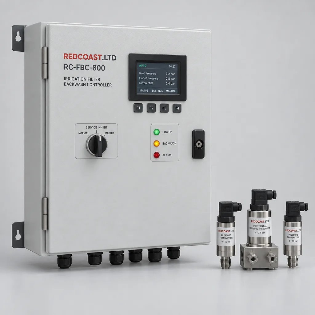
The RC-FBC-800 is a mains-powered irrigation filter backwash control and monitoring system from REDCOAST.LTD, developed for landscape irrigation headworks, golf courses, nurseries, sports facilities, and campus water infrastructure. It combines an outdoor control cabinet, pressure instrumentation, valve interfaces, local operating controls, and a web platform with mobile access. The system addresses blocked filters, unnecessary flushing, repeated cleaning failures, and maintenance teams having insufficient information about conditions at the filtration station. REDCOAST.LTD delivers the complete control solution and develops the underlying signal-conditioning, valve-driver, and controller PCBs to match the project; the specifications below define a proposed build-to-order configuration, with final performance and acceptance requirements confirmed during engineering.
Key Features
- Eight independently sequenced filter stations: Control one to eight compatible automatic filter units, with two additional outputs for master or pressure-sustaining pilot valves.
- Dedicated differential-pressure measurement: A separate differential-pressure transmitter measures filter restriction, while upstream and downstream transmitters provide operating-pressure context.
- Multiple cleaning triggers: Initiate backwash by sustained differential pressure, elapsed operating time, scheduled time, or an authorized local or remote request.
- Hydraulic permissives before cleaning: Check minimum inlet pressure, pump-ready status, and external process permissions before opening the selected backwash valve.
- Cleaning-result assessment: Record pressure before and after each sequence, evaluate recovery under comparable flow conditions, and identify repeated unsuccessful cleaning.
- Measured backwash water accounting: Accept a dedicated drain-line meter input to total actual cleaning water separately from irrigation delivery.
- Independent local operation: Execute stored sequences and protective logic without internet access, with buffered records uploaded after connectivity returns.
- Integrated maintenance workflow: Provide alarm acknowledgment, service notes, configuration history, pressure trends, and filter-station status through the web platform and mobile interface.
Technical Architecture
The reference package includes one RC-FBC-800 cabinet, two 0–16 bar line-pressure transmitters, one 0–2.5 bar differential-pressure transmitter, and configured control software. Inside the cabinet, a REDCOAST.LTD controller PCB handles deterministic sequencing and local data storage. A dedicated analog front end reads four 4–20 mA channels, detects out-of-range signals, and applies configurable filtering to avoid reacting to short hydraulic transients. A separate protected output board operates 24 V DC pilot solenoids and monitors electrical faults. Pressure instruments connect to accessible, isolatable sampling points; the differential-pressure transmitter requires appropriate common-mode pressure capability and a service manifold for isolation, equalization, and zero checks.
The control sequence moves through idle, trigger validation, permissive checking, master-valve preparation, individual filter cleaning, pressure recovery, and result verification. Only one filter station backwashes at a time in the standard program. A sustained high differential pressure requests a cycle, but inadequate inlet pressure or a missing pump-ready signal prevents it from starting. After cleaning, the controller allows the line to stabilize before assessing the remaining pressure drop. Repeated unsuccessful sequences generate a maintenance alarm and stop automatic retries at the configured limit. Time- and differential-pressure-based flushing, modular station outputs, and continuous-flushing alarms are established commercial approaches documented by Netafim's backflush controller range.
An embedded communications gateway exchanges measurements, alarms, and operating records with the platform. Remote commands pass through the same local permissives as front-panel commands, and cloud access cannot override a physical service inhibit. Records include trigger source, active station, pre- and post-cleaning pressure, elapsed cleaning time, measured drain volume when a meter is installed, and fault status. Pressure recovery is an indicator of cleaning effectiveness, not proof of filtration quality: changing irrigation flow also changes pressure loss, so comparisons use similar flow conditions where possible.
Connectivity & Power
The RC-FBC-800 uses AC 100–240 V, 50/60 Hz power from the existing irrigation headworks or pump-house electrical distribution. An internal isolated 24 V DC supply powers the electronics, transmitters, and compatible pilot solenoids. Typical electronics and instrumentation demand is 15–25 W before external valve loads; the reference cabinet has a 120 W DC supply and a maximum specified AC input budget of 180 W with its optional 40 W anti-condensation heater. Irrigation pumps, booster pumps, and motorized filter scanners require their own motor circuits and starters. The controller exchanges permissive or run-request signals with those starters through interposing interfaces.
Ethernet is the preferred connection where site networking exists. Optional 4G LTE provides backhaul for outdoor headworks without a nearby network connection; modem bands and antennas are selected for the installation. Isolated RS-485 supports Modbus RTU integration with meters and compatible plant equipment, while Modbus TCP and MQTT over TLS provide integration paths to supervisory systems. Remote access uses individual accounts and role permissions. On loss of mains power, outputs de-energize; valve hydraulic arrangements must be selected so that their de-energized positions produce the agreed operating condition. Power restoration starts with pressure and permission checks rather than automatically resuming an interrupted valve movement.
Protection & Reliability
The cabinet is specified with an IP66 enclosure design target, sealed bottom cable entries, segregated mains and signal wiring, and replaceable terminal blocks. Its galvanized steel substrate receives a smooth matte powder-coated finish, with an optional fluorocarbon topcoat system for more demanding outdoor exposure. Conformal coating on selected PCB assemblies, protected field interfaces, surge protection, and an anti-condensation heater address moisture and electrical disturbances. Final ingress performance depends on the completed enclosure, display, glands, and installation and must be verified on the delivered assembly.
The electronics design range is −20 to +55 °C, while the standard wet instrumentation package is intended for nonfreezing water between +5 and +50 °C. Cold locations need insulated or heated instrumentation arrangements, or seasonal drainage; a cabinet heater does not protect exposed water lines. Direct sun requires a sunshade and thermal review. Coastal installations require a coating and connector specification appropriate to the actual exposure, and mounting loads are checked against local wind conditions. Replaceable power supplies, output boards, sensors, and stored configuration backups support repair throughout the equipment lifecycle. Warranty duration, spare-parts coverage, and support response times are agreed in the supply contract.
Application Scenarios
Municipal parks and landscaped public spaces
Install the controller beside an existing automatic filter bank serving drip irrigation and sprinkler zones. Pressure trends and cleaning alarms give landscape teams a practical way to identify developing restrictions before they affect large planted areas.
Golf courses and sports complexes
Connect the filter controller to pump-ready signals and the irrigation management system at the central headworks. Backwash requests can be coordinated with irrigation demand so that cleaning occurs with adequate pressure and an understood effect on downstream delivery.
Commercial nurseries and greenhouse campuses
Use individual station sequencing for multi-filter installations supplying propagation beds, container plants, and greenhouse irrigation. Where fertilizer injection is present, a hardwired cleaning-active signal can request a dosing pause, subject to the dosing controller's approved interlock design.
Business parks and university campuses
Retrofit filtration monitoring without replacing the existing landscape scheduling controller. Facilities teams can bring pressure, cleaning events, and maintenance alarms into their site dashboard while retaining local operation at the headworks.
Reclaimed-water landscape irrigation
Monitor automatic filtration stations supplied from an approved nonpotable water network. Frequent unsuccessful cleaning can prompt inspection of the filter, pilot valves, or upstream pretreatment, while water-quality compliance remains the responsibility of the treatment and monitoring process.
Case-style Examples
The following examples illustrate configuration and commissioning choices; they are not claims of completed installations or measured customer savings.
Four-filter park irrigation retrofit
A park operates four automatic disc filters but maintenance staff only see a mechanical pressure gauge during site visits. A proposed installation uses four station outputs, one master pilot output, three pressure transmitters, Ethernet, and separate delivery and backwash meter inputs. If measured backwash flow is 6 m³/h and each filter cleans for 30 seconds, each cleaning uses approximately 50 liters, or 200 liters for a four-filter sequence, excluding additional master-valve flushing. Recording actual meter totals lets the operator compare cleaning frequency and water consumption against the previous operating baseline instead of relying on an assumed savings percentage.
Nursery media-filter cleaning supervision
A nursery has six media vessels and needs to know when a repeated backwash cycle is failing to restore normal differential pressure. The proposed configuration uses six sequential outputs, low-pressure inhibition, a dosing-pause interface, and 4G connectivity. Commissioning establishes each vessel's required cleaning flow and duration from its manufacturer's data; the controller then records sequence completion and issues a service alarm when recovery remains inadequate. The expected operational benefit is a clearly assigned maintenance task with supporting pressure records, rather than unnoticed repeated flushing.
Customization & Selection Guide
Start with the filter manufacturer's model, number of vessels, cleaning mechanism, operating pressure, required backwash flow, and valve actuation details. Screen filters, disc filters, and media vessels need different sequencing and hydraulic conditions. The reference electronics drive nonlatching 24 V DC pilot solenoids; existing 24 V AC coils or DC latching coils require the corresponding replacement driver board and power-stage configuration. Motor-driven suction scanners require a separate starter interface and motion feedback suited to the scanner mechanism.
Select pressure instruments according to actual line pressure, expected differential pressure, fluid compatibility, and allowable overpressure. Use the dedicated differential-pressure transmitter when cleaning thresholds are small relative to the line-pressure range; subtracting two wide-range pressure readings can introduce significant error. A basic package provides pressure-based sequencing and local operation. Add a drain meter for measured backwash consumption, delivery metering for flow-context comparisons, and additional valve-position feedback where actuator verification matters.
Hydraulic capacity belongs to the selected filter bank and piping design, not to the controller's station count. Confirm whether the remaining filters can supply downstream demand and cleaning flow simultaneously. If they cannot, coordinate a temporary irrigation pause or engineer a separate cleaning-water arrangement. REDCOAST.LTD can engineer an optional matched filter skid, but vessel size, filtration rating, manifold capacity, and drain requirements are specified separately after water analysis and hydraulic review.
Deployment & After-sales
Installation begins with an electrical and hydraulic survey, an agreed I/O schedule, and a documented sequence of operation. Mount the cabinet above the site's expected flood level, provide accessible isolation, route signal cables separately from motor power, and position pressure taps so that trapped air and blocked sensing lines can be serviced. Route backwash discharge to a permitted drain or recovery system sized for the instantaneous cleaning flow. Hydraulic isolation and depressurization remain necessary before servicing instruments or filter equipment.
Factory acceptance checks cover analog-input simulation, output loading, abnormal pressure conditions, lost communications, interrupted power, alarm routing, and configuration recovery. Site acceptance verifies actual valve direction, cleaning pressure, pressure stabilization, drain capacity, and coordination with irrigation or dosing equipment. Project schedules separate design approval, any new PCB development, prototype verification, production, and commissioning; a delivery date is committed after the hardware scope and component availability are confirmed. Handover includes wiring drawings, a Modbus register map, configuration backups, an operator guide, maintenance recommendations, and contracted remote support.
Standards & Compliance
The engineering and test plan uses IEC 60529 for enclosure ingress classification, IEC 61010-1 for applicable measurement and control equipment safety requirements, and IEC 61326-1 for electromagnetic compatibility of measurement and control equipment. These references identify assessment directions; they do not represent completed certification of this proposed configuration. Required declarations, laboratory reports, radio approvals, and material restrictions are identified for the final destination and delivered hardware.
For a package including automatic screen or disc filters, ISO 9912-3:2013 provides relevant construction requirements and test methods. Its scope does not establish filtration efficiency or capacity, so neither those characteristics nor complete skid compliance can be inferred from the controller. Filter performance, pressure-containing equipment, backflow prevention, electrical installation, and discharge arrangements require their own applicable assessments. The system does not disinfect water or establish its suitability for potable use.
Why REDCOAST.LTD
REDCOAST.LTD brings the cabinet, instrumentation interfaces, operating logic, web platform, and mobile workflow into one project delivery. Its in-house hardware development includes new PCB layouts, pressure-signal conditioning, protected solenoid drivers, isolated communications, and power-management circuitry, allowing electrical interfaces and operating behavior to be adapted to the actual filtration station. This gives owners and integrators a defined route for retrofits, additional measurements, and integration with existing irrigation or facility software. Project documentation ties each selected configuration to its operating limits and acceptance checks, so procurement decisions rest on an explicit technical scope.
Contact REDCOAST.LTD with your filter models, valve voltages, operating pressures, water-source details, and integration requirements to configure an RC-FBC-800 solution.
Specifications
Controller and Sequencing
- Model and specification status
- RC-FBC-800; proposed build-to-order reference configuration
- Filter stations
- 1–8 independently sequenced stations
- Additional master pilot outputs
- 2 outputs
- Backwash duration per station
- 5–600; 1-second setting increments s
- Interstation recovery delay
- 0–300 s
- Periodic cleaning interval
- 15–1440; elapsed operating-time mode min
- Unsuccessful sequence retry limit
- 1–5; reference setting 2 before lockout and alarm sequences
Pressure Instrumentation
- Upstream and downstream pressure transmitters
- 2 × 0–16; 4–20 mA output bar
- Line-pressure reference accuracy
- ±0.25% full scale at 20–25 °C
- Dedicated differential-pressure transmitter
- 0–2.5; 4–20 mA output; common-mode working pressure at least 16 bar bar
- Differential-pressure reference accuracy
- ±0.5% of 2.5-bar full scale at 20–25 °C
- Differential-pressure trigger
- 0.10–1.50; initial commissioning value 0.50, subject to filter requirements bar
- Trigger persistence delay
- 1–120 s
- Minimum inlet-pressure permissive
- 0.5–10.0; set to the filter manufacturer's cleaning requirement bar
Field Inputs and Outputs
- Analog inputs
- 4 × 4–20 mA; 16-bit conversion; 3 allocated to standard pressure instruments
- Digital inputs
- 8 × optically isolated 24 V DC
- Meter pulse inputs
- 2 × 0–100 Hz; configurable pulse scaling
- Standard solenoid outputs
- 10 × 24 V DC, nonlatching; 0.5 A maximum per output
- Combined solenoid output limit
- 2.0; standard logic permits one filter station plus configured master outputs A
- Auxiliary dry-contact relays
- 4 × SPDT; 30 V DC, 1 A resistive maximum; external interposing interface for motor starters
- Pressure sampling interval
- 100 ms
Mains Power
- Input voltage
- AC 100–240, single phase V
- Input frequency
- 50/60 Hz
- Internal DC supply
- 24 V DC, 5 A; 120 W nominal
- Typical electronics and sensor consumption
- 15–25; excludes solenoids and heater W
- Maximum cabinet input design budget
- 180; includes optional heater, excludes external pump and scanner motors W
- Optional anti-condensation heater
- 40; thermostatically controlled W
- Power-loss output state
- All solenoid outputs de-energized; fresh permissive checks on restart
Connectivity and Data
- Ethernet
- 1 × 10/100BASE-T
- Serial interface
- 1 × isolated RS-485; 9600–115200 baud; Modbus RTU
- IP protocols
- Modbus TCP; HTTPS; MQTT over TLS 1.2 or later
- Optional cellular modem
- 4G LTE Cat 1 bis; installation-specific band selection
- Local trend retention design
- 90 days at 60-second logging for up to 16 numeric channels
- Event log capacity
- 100000; circular storage records
- User access roles
- Viewer, operator, maintenance, administrator
Enclosure and Environment
- Cabinet dimensions
- 500 × 400 × 220; height × width × depth, excluding mounting brackets mm
- Cabinet ingress design target
- IP66; verification required on the completed assembly
- Electronics operating design range
- −20 to +55; shaded installation and configuration-specific thermal verification °C
- Standard wet-instrument water temperature
- +5 to +50; no freezing °C
- Ambient relative humidity
- 5–95; noncondensing inside cabinet % RH
- Cabinet construction and finish
- 1.5 mm galvanized steel; smooth matte RAL 7035 powder coating
- Local operator interface
- 4.3-inch display; sealed function keys; physical service-inhibit switch
Capabilities — configurable per project
Specifications are tailored to each project — the options below show what we can support.
Filter Control Package
- 2-station retrofit package
- 4-station automatic filter bank
- 8-station automatic filter bank
- Motor-scanner interface with external starter and feedback
Valve Driver Hardware
- 24 V DC nonlatching pilot solenoids
- 24 V AC pilot solenoids with alternative driver and transformer
- DC latching pilot solenoids with matched pulse-driver PCB
Monitoring Package
- Inlet, outlet, and differential pressure
- Pressure plus delivery and backwash water meters
- Pressure and metering plus valve-position feedback
Communications and Platform
- Ethernet with hosted web and mobile management
- 4G LTE with hosted web and mobile management
- Ethernet with on-premises deployment
- Modbus integration with an existing supervisory system
Installation Package
- Wall-mounted cabinet and sensor kit
- Outdoor pedestal with sunshade
- Coastal coating and connector package
- Cold-climate cabinet with separately engineered wet-line frost protection
Related solution guidance
Environmental Monitoring
Deploy environmental monitoring stations with sensors, solar power, gateways, dashboards, alarms and data integration for city and industrial sites.
Power and Connectivity
How to choose power, battery, solar, NB-IoT, LTE, LoRaWAN, gateways and monitoring strategy for outdoor IoT infrastructure.
Solar IoT Guide
A design guide for solar-powered outdoor IoT: load calculation, battery autonomy, low-power firmware, telemetry and maintenance planning.
Frequently Asked Questions
What does an automatic irrigation filter backwash controller do?
It starts and sequences filter cleaning when differential pressure, elapsed operating time, or another configured trigger indicates that cleaning is needed. The RC-FBC-800 also checks operating permissions, records pressure recovery, and reports repeated cleaning failures. It manages the filter's cleaning process; filtration rating and hydraulic capacity depend on the connected filter equipment.
Can the RC-FBC-800 retrofit an existing disc, screen, or media filter bank?
Yes, a retrofit can be engineered when the filter's valve controls, cleaning sequence, instrumentation, and hydraulic requirements are documented. The reference model has eight filter-station outputs and two additional master pilot outputs. Different coil voltages, latching valves, or motorized scanners require matched interface hardware rather than a software-only setting.
What differential-pressure setting should trigger irrigation filter cleaning?
The correct value comes from the filter manufacturer's requirements and the site's clean-filter pressure loss at operating flow. The RC-FBC-800 provides a 0.10–1.50 bar setting range, with 0.50 bar as an initial commissioning value rather than a universal recommendation. A persistence delay helps reject brief pressure transients, and low inlet pressure inhibits ineffective cleaning.
Can irrigation continue while the filters are being backwashed?
It can continue only when the filter arrangement and water supply can maintain the required downstream pressure while also providing cleaning flow. Sequential backwashing reduces simultaneous cleaning demand, but it does not guarantee uninterrupted irrigation. Where available capacity is insufficient, the controller can coordinate a cleaning window or request an irrigation pause through the agreed interface.
How much water does an automatic backwash cycle use?
Consumption depends on measured cleaning flow, cleaning duration, the number of filters, and any additional master-valve flushing. For example, 6 m³/h for 30 seconds equals 50 liters per filter, so four such cleaning steps total approximately 200 liters before other flushing losses. A dedicated drain-line meter provides actual consumption; valve-open time alone is only sufficient for an estimate when flow is known.
Does the controller need solar power or a permanent internet connection?
This configuration uses AC 100–240 V from the existing site electrical supply and does not require solar panels. Stored sequences and local protective logic operate without an internet connection, while Ethernet or optional 4G provides remote monitoring. A mains outage de-energizes the outputs, and restoration initiates fresh pressure and permission checks.
Can REDCOAST.LTD customize the hardware and integrate the system with existing software?
REDCOAST.LTD can develop project-specific PCBs for pressure acquisition, solenoid driving, power management, and communications, alongside the cabinet, web platform, and mobile workflow. Integration options include Modbus RTU, Modbus TCP, and MQTT over TLS. Final interfaces, environmental performance, compliance evidence, delivery dates, and acceptance tests are defined for the ordered configuration.