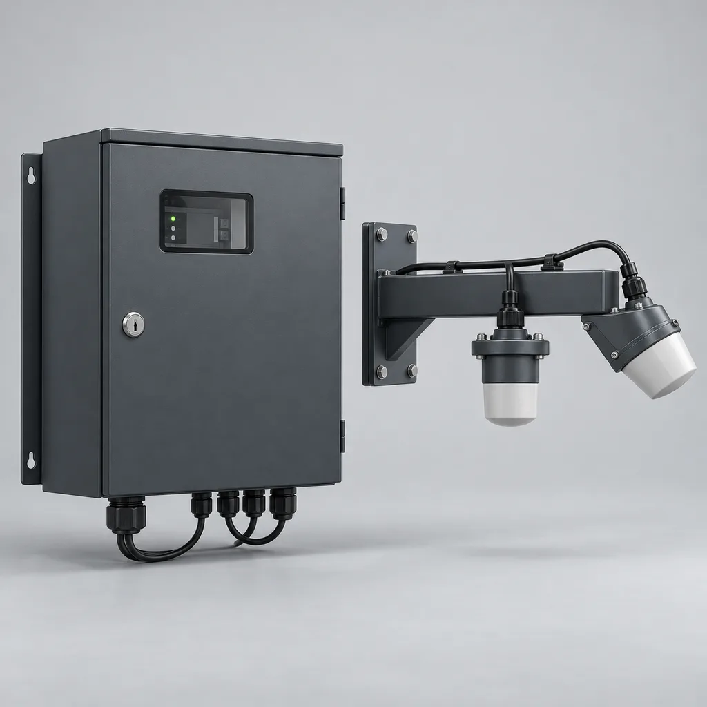
Overview
The RC-OCF-600 is a permanent, grid-powered open-channel flow monitoring solution for utilities, industrial estates, drainage authorities and irrigation operators with electricity available at the measurement site. It combines non-contact surface-velocity radar, radar water-level measurement, an edge controller, a Web management platform and a mobile app to turn individual channel readings into usable flow histories and maintenance alerts. Operators can investigate unexpected discharge, compare inflow and outflow, and document event volumes without placing the primary sensors in dirty water. REDCOAST.LTD delivers the complete system and develops the controller, isolated sensor-interface and power-monitoring PCBs around project requirements. The specifications below define a proposed project configuration; final performance and acceptance limits are established through sensor selection, site survey and commissioning.
Key Features
- Two independent hydraulic measurements: Record water level and signed surface velocity together, helping operators distinguish a rising channel from faster discharge.
- Non-contact sensor installation: Mount the radar heads above the flow to reduce direct exposure to sediment, floating debris and wastewater deposits.
- Site-specific flow calculation: Combine surveyed channel geometry with a validated surface-to-mean velocity relationship instead of applying one correction factor to every installation.
- Useful volume records: Maintain separate forward and reverse totals, event start and end times, and data-validity flags for operational reporting.
- Local operation during network loss: Continue measurement, calculation and logging while the mains supply remains available, then upload buffered records after communication returns.
- Actionable alarms: Configure high level, high flow, reverse flow, persistent unexpected dry-weather discharge, sensor faults and cabinet access notifications.
- SCADA and sampling interfaces: Provide Modbus data, isolated analog inputs and dry-contact outputs for supervisory systems or compatible automatic samplers.
- Hardware and software customization: Adapt PCB interfaces, cabinet layout, reporting units, alarm workflows and API mappings within one coordinated delivery.
Technical Architecture
The reference station uses a 24 GHz Doppler surface-velocity sensor aimed obliquely along the flow and a separate 80 GHz radar level sensor aimed vertically at a clear water surface. The level measurement establishes water depth relative to a surveyed datum; the velocity sensor measures motion at the surface rather than the mean velocity through the entire section. Commercial instruments demonstrate this established approach, including measurement-quality and installation diagnostics. See the manufacturer's OTT SVR 100 specifications for an independent technology reference.
The edge controller calculates discharge using Q = A(h) × k(h) × vs, where A(h) is wetted area from the surveyed cross-section, vs is measured surface velocity and k(h) is the site-specific conversion to mean velocity. A universal coefficient is not assumed: calibration must address the operating depth range and hydraulic conditions. This distinction is also explained in the manufacturer's SOMMER discharge-measurement documentation. Bends, changing sediment beds, strong backwater, foam, ice and an insufficiently textured water surface can invalidate the relationship or weaken the radar return; such periods require quality flags or a different measurement method.
REDCOAST.LTD develops the station's processor carrier, isolated RS-485 interfaces, analog acquisition circuits, relay interface and DC distribution monitoring hardware. Qualified radar instruments remain identifiable components rather than being represented as proprietary semiconductor technology. Firmware timestamps accepted samples, applies configurable averaging and alarm persistence, and stores the underlying level, velocity, calculated flow and configuration revision. Invalid intervals are marked as gaps and excluded from verified volume totals; any authorized estimates remain separately identified. The Web platform combines site maps, trends, event reports and maintenance records, while the mobile app supports alarm acknowledgment and inspection notes.
Connectivity & Power
The station connects to a dedicated AC 100–240 V, 50/60 Hz supply and uses an isolated 24 V DC internal rail. The reference load is 20–40 W during normal measurement and communication, equivalent to approximately 0.48–0.96 kWh per day before optional heating. A 50 W thermostatic anti-condensation heater brings the configured maximum input budget to 100 W. The standard cabinet contains no solar charging equipment; installation is intended for powered drainage assets, treatment works, industrial sites and canal control buildings.
Ethernet is preferred where a managed site network is available. A regional-band 4G LTE modem provides an alternative uplink or optional failover, and fiber can be introduced through an external industrial media converter for long cable routes. Modbus RTU connects field devices, Modbus TCP serves local SCADA, and MQTT over TLS or an HTTPS API transfers application data. Unencrypted industrial protocols remain on a segregated site network rather than being exposed directly to the internet. Connectivity loss does not stop local logging, but a mains outage stops measurement unless the customer's backed-up AC circuit supplies the station.
Protection & Reliability
The enclosure design targets IP66 for the completed cabinet and at least IP67 for selected sensor heads. These ratings must apply to the assembled configuration, including glands and connectors; the installation remains above the design flood level. Steel cabinets and mounting arms receive hot-dip galvanizing as the corrosion-protection base, followed by a smooth matte powder-coated or fluorocarbon-painted finish. Coastal projects require a coating system and fastener selection matched to the actual exposure.
The reference cabinet ambient range is -20 to +55 °C, with a sunshield and thermal review required for exposed sites. Dust protection, condensation management, separated mains and signal wiring, coordinated surge protection and protective-earth bonding form part of the installation design. Bracket stiffness and anchorage are checked for local wind and vibration loads because sensor movement can affect measurement. Non-contact installation reduces fouling but does not eliminate maintenance: inspect radar faces, cables, seals and the channel cross-section after significant events. No universal corrosion life, wind rating or maintenance-free service life is assumed.
Application Scenarios
Municipal stormwater outfalls: Install the station over an accessible open channel near a powered drainage asset. Level, velocity and event-volume records help compare storm responses and identify persistent flow during nominally dry periods for follow-up inspection.
Wastewater treatment inlet channels: Monitor a suitable straight reach outside classified hazardous areas to understand daily loading and wet-weather peaks. The flow history supports operational planning, while independent plant controls retain responsibility for process protection.
Industrial estate drainage: Measure discharge through a shared collection channel and align event timestamps with tenant operating schedules. The station identifies hydraulic anomalies; pollutant identification requires separate water-quality instruments or laboratory samples.
Irrigation delivery and return canals: Position stations near powered gates or pumping compounds to compare delivered and returned water volumes. These records support irrigation scheduling and water accounting, provided each measurement section is independently surveyed and validated.
Detention-basin outlet channels: Log the discharge hydrograph downstream of a storage basin with a nearby electrical supply. Engineers can compare events over time and investigate changed drawdown behavior without relying on water level alone.
Case-style Examples
The following are illustrative configurations, not claims of completed customer installations or measured savings.
Industrial drainage outlet retrofit: An estate operator has water-level alarms but cannot distinguish slow ponding from a large discharge event. A single-channel RC-OCF-600, two radar heads, Ethernet connectivity and a sampler-trigger contact add flow trends and event records using existing mains power. After reference measurements establish the usable range, the operator can review the timing and estimated volume of unusual events alongside inspection and sampling results.
Irrigation canal water accounting: A canal operator needs to reconcile delivery and return flows near two powered control buildings. Two stations use surveyed trapezoidal profiles, 4G uplinks and synchronized reporting intervals, with separate validation at each section. The resulting time series supports comparison after allowing for travel time, intermediate withdrawals and storage changes; a difference between the stations is not automatically classified as leakage.
Treatment-works wet-weather investigation: A plant wants to understand rapid changes in an open inlet channel during rainfall. A station with a rain-gauge pulse input records ten-second data and reports one-minute summaries to SCADA. Engineers can correlate rainfall with measured hydraulic response, while periods affected by foam, surcharge or poor radar signal remain visibly flagged for review.
Customization & Selection Guide
Begin with a channel drawing, expected minimum and maximum levels, velocity estimates, photographs, flood elevation and available power and communications. The baseline installation serves one measurement section with one velocity radar and one level radar. A stable, relatively uniform reach is preferable; the entire radar footprint must remain on representative moving water across the operating range.
Specify additional velocity heads only when the width or velocity distribution justifies them, with a separate hydraulic assessment and revised power budget. Where extremely smooth water, persistent foam, full-pipe surcharge or complex reversing flow dominates, select a different sensing arrangement rather than forcing a surface-radar solution. For existing SCADA, a gateway-only deployment may be sufficient; distributed asset owners can select the Web platform and mobile workflow. Define report units, data ownership, retention, integration responsibilities and any regulatory acceptance requirements before ordering.
Deployment & After-sales
Deployment starts with a hydraulic and electrical site review, followed by bracket design, cabinet assembly, configuration and factory acceptance checks. Commissioning establishes the level datum, channel geometry, radar alignment, network settings and alarm thresholds, then compares calculated discharge with suitable independent reference measurements across representative flows. Acceptance records should distinguish sensor checks from the uncertainty of the installed flow estimate.
Delivery scheduling is agreed after the sensor bill of materials and interface requirements are frozen; new PCB development and external testing require separate milestones. Handover includes wiring drawings, an I/O list, configuration backups, operating instructions, a commissioning record and administrator training. Support can cover remote diagnostics, replacement sensor setup, firmware maintenance and revised channel profiles after civil works or sediment removal. Warranty duration, spare-parts provision and response times are stated in the project quotation.
Standards & Compliance
Gauging-station siting and operating procedures can be specified with reference to ISO 18365:2013, confirmed in 2025. Independent reference measurements may use appropriate velocity-area procedures; their method and uncertainty must match the site. Neither a sensor datasheet nor a cloud report establishes regulatory acceptance of the installed discharge measurement.
The project test plan should address enclosure ingress protection under IEC 60529, electrical measurement-equipment safety under IEC 61010-1 and applicable amendments, and emissions and immunity under IEC 61326-1:2020. Applicable radio approvals, material restrictions and market-specific conformity documentation are selected for the destination and final configuration. These are engineering and assessment references, not claims that this proposed model already holds certification. The reference configuration is for non-hazardous locations; classified sewer environments require a separately assessed equipment selection.
Why REDCOAST.LTD
REDCOAST.LTD combines field hardware, embedded software, a Web platform and a mobile app into one project delivery. Its in-house PCB and board-level design capability allows sensor interfaces, isolation, power supervision and local I/O to be engineered around the customer's channel and operating workflow. This makes it practical to support an existing asset-management system, add a specific sampling interface or adjust the cabinet without treating every requirement as an external integration project. Clear component specifications, commissioning evidence and maintainable documentation keep customization tied to a usable long-term installation.
Contact REDCOAST.LTD with your channel dimensions, expected flow conditions and integration requirements to request a customized RC-OCF-600 proposal.
Specifications
Hydraulic Measurement
- Measurement Sections
- 1; one surface-velocity radar plus one level radar
- Surface-Velocity Measurement Band
- -10 to -0.15 and +0.15 to +10; subject to surface conditions m/s
- Sensor-to-Water Distance
- 0.5–12; both radar footprints must remain unobstructed m
- Radar Frequencies
- 24 velocity / 80 level; destination-approved variants GHz
- Level-Sensor Reference Accuracy Target
- ±5 under specified reference conditions; excludes datum and mounting errors mm
- Recorded Resolution
- 1 mm level; 0.001 m/s surface velocity; resolution is not accuracy
- Flow Calculation and Units
- Q = A(h) × k(h) × vs; L/s or m³/s; forward/reverse totals in m³
Grid Power
- AC Input Voltage
- 100–240 V AC
- Input Frequency
- 50/60 Hz
- Normal Station Consumption
- 20–40; one measurement section, heater off W
- Configured Maximum Input
- 100; including 50 W heater W
- Internal DC Power Supply
- 24 V DC / 5 A rated; final loading subject to thermal derating
- Anti-Condensation Heater Option
- 50; thermostatically controlled W
Interfaces & Communications
- Wired Network
- 1 × 10/100BASE-T Ethernet
- Cellular Uplink Option
- 4G LTE Cat 1 or Cat 4; regional band selection
- Sensor Serial Ports
- 2 × isolated RS-485; Modbus RTU; 1200–115200 baud
- Analog Inputs
- 4 × isolated 4–20 mA; 16-bit conversion
- Digital Inputs
- 4 × dry-contact inputs; 0–100 Hz pulse counting
- Relay Outputs
- 2 × changeover dry contacts; 1 A at 30 V DC resistive
- Integration Protocols
- Modbus TCP; MQTT over TLS 1.2/1.3; HTTPS REST API
Logging & Platform
- Record Interval
- 10–900; default 60; dependent on sensor update rate s
- Local Storage
- 16 GB
- Reference Local Retention
- 365 at 60-second intervals for 16 numeric channels; no images days
- Report Intervals
- 1 / 5 / 15 / 60 minutes; daily totals
- Alarm Persistence
- 10–3600; evaluated on valid measurement updates s
- Data Exports
- CSV / JSON; timestamps, quality flags and configuration revision
Enclosure & Environment
- Cabinet Protection Target
- IP66; complete assembly subject to ingress testing
- Sensor Protection Selection
- IP67 minimum; installed above design flood level
- Cabinet Ambient Design Range
- -20 to +55; sunshield and thermal verification for exposed sites °C
- Reference Cabinet Dimensions
- 600 × 450 × 250; height × width × depth mm
- Steel Cabinet Construction
- 1.5–2.0 steel; hot-dip galvanized base plus smooth matte topcoat mm
- Topcoat Selection
- Powder coating or fluorocarbon paint; RAL 7016 / RAL 7035
Installation & Commissioning
- Level-Radar Orientation
- Vertical; 0° nominal from vertical
- Velocity-Radar Mounting Angle
- 30–60 below horizontal; 45 nominal; sensor-specific verification degrees
- Standard Sensor Cable Lengths
- 10 / 20 / 30; shielded outdoor cable m
- Reference Section Profiles
- Rectangular / trapezoidal / surveyed irregular open channel
- Initial Field Inspection Interval
- 1–3; shorten after floods, construction or sediment changes months
- Volume Data Classification
- Valid / estimated / invalid; missing intervals excluded from verified totals
Capabilities — configurable per project
Specifications are tailored to each project — the options below show what we can support.
Measurement Layout
- One velocity radar and one level radar
- Two velocity radars with hydraulic weighting study
- Three velocity radars with hydraulic weighting study
Network Architecture
- Ethernet to site SCADA
- 4G LTE to Web platform
- Ethernet with 4G failover
Operational Interfaces
- Alarm relay to supervisory system
- Volume-pulse output to automatic sampler
- Rain-gauge pulse input and event correlation
Software Delivery
- SCADA gateway with local logging
- Hosted Web platform and mobile app
- Customer-hosted platform with documented API
Related solution guidance

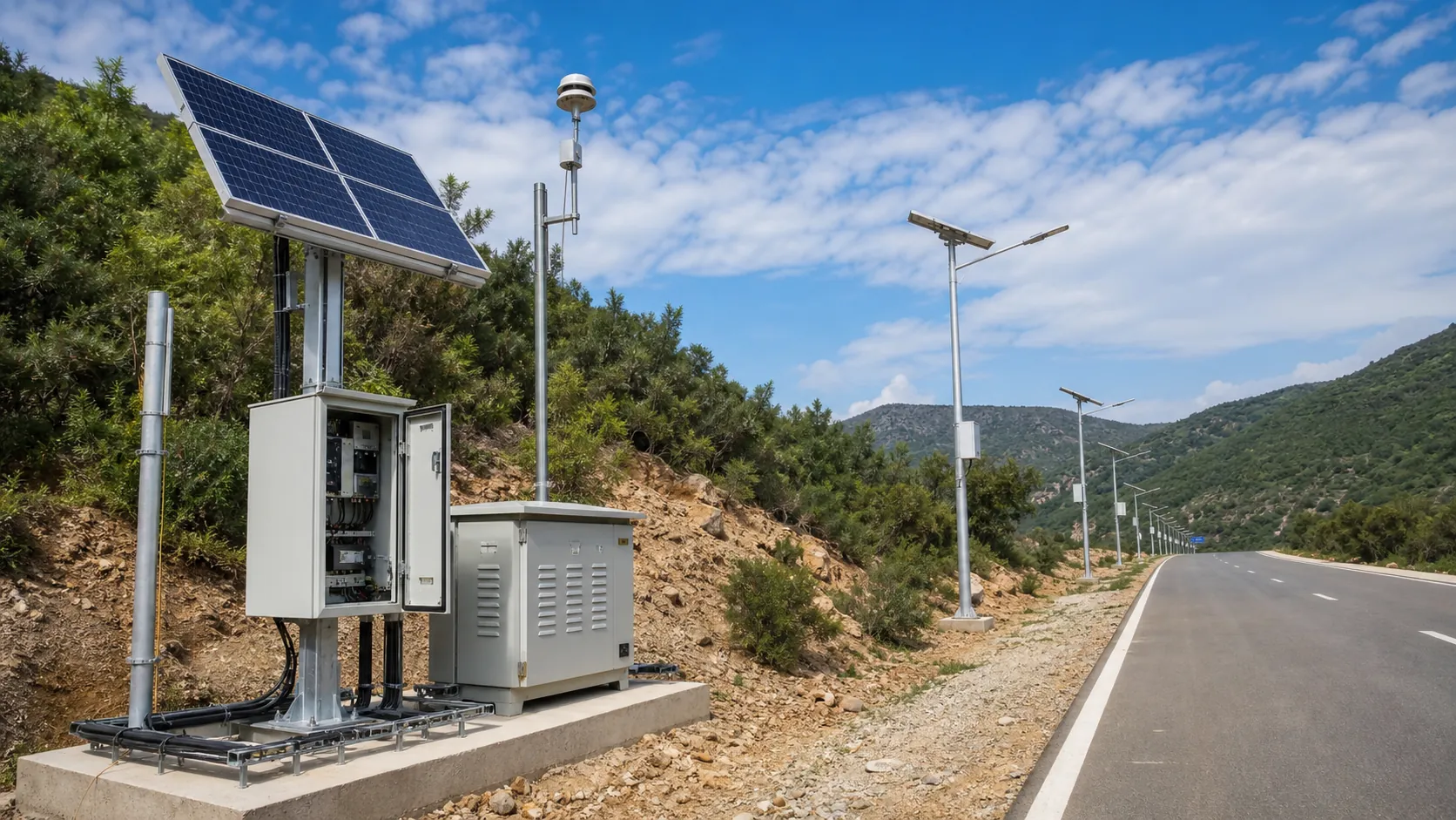
Environmental Monitoring
Deploy environmental monitoring stations with sensors, solar power, gateways, dashboards, alarms and data integration for city and industrial sites.
Power and Connectivity
How to choose power, battery, solar, NB-IoT, LTE, LoRaWAN, gateways and monitoring strategy for outdoor IoT infrastructure.
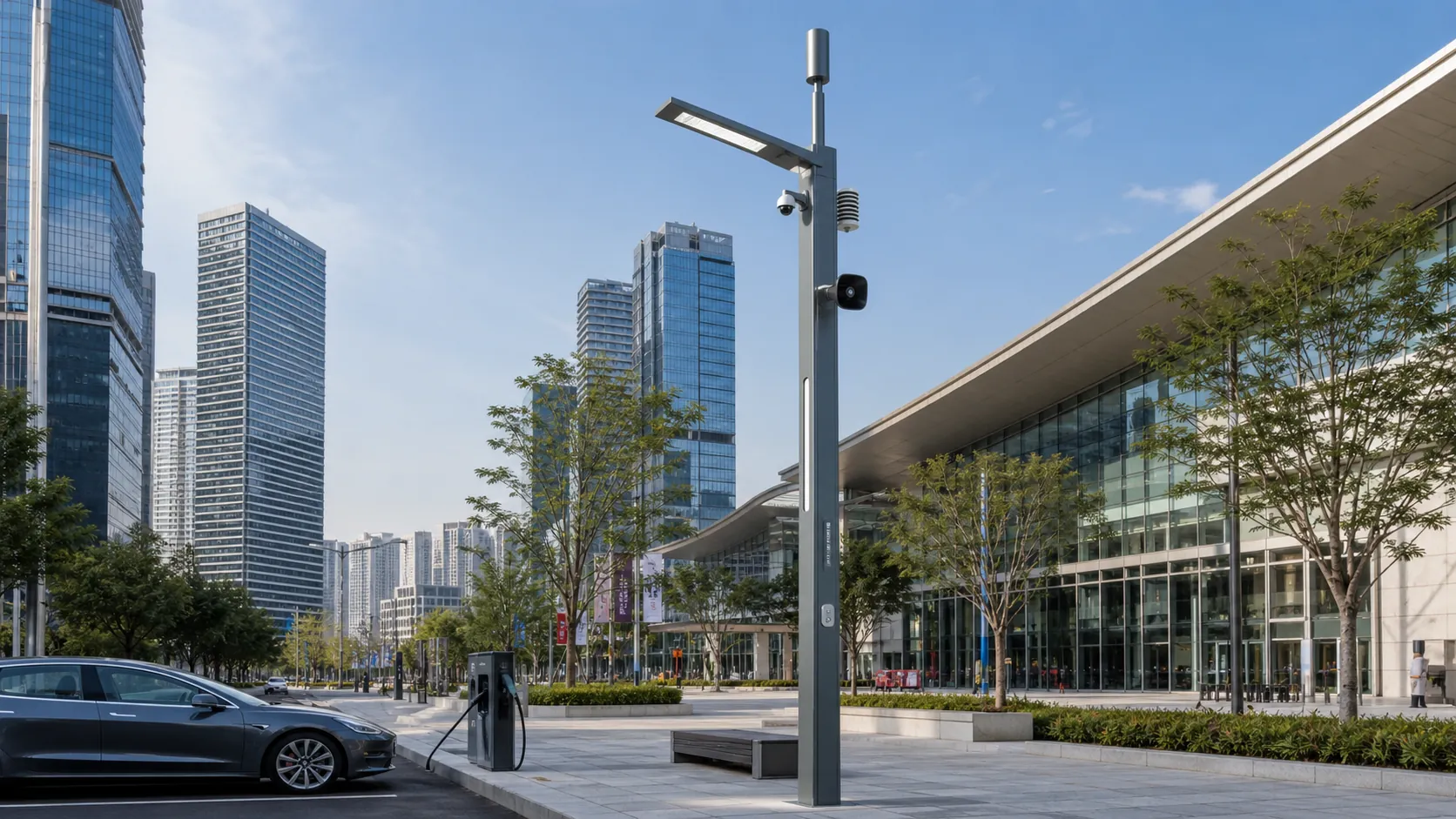
Campuses
Campus IoT for lighting, parking, safety, smart poles, environmental data and facility maintenance workflows.
Frequently Asked Questions
How does a non-contact radar open-channel flow meter calculate flow?
A surface-velocity radar measures water motion while a separate level radar determines depth relative to a surveyed datum. The controller calculates discharge from wetted area, surface velocity and a site-specific conversion to mean velocity. Channel geometry and the conversion relationship must be validated; surface velocity alone is not a volumetric flow measurement.
Can RC-OCF-600 measure very slow water, reverse flow or a full sewer pipe?
The reference surface-velocity band is 0.15–10 m/s in either direction, subject to a usable radar return and the selected sensor. Water below the validated velocity threshold, persistent foam, ice or complex reversing flow may require another method. A surcharged full pipe has no exposed free surface, so this configuration is unsuitable for measuring its flow.
What accuracy can I expect from the installed flow monitoring station?
The proposed level-sensor target is ±5 mm under defined reference conditions, but that is not the accuracy of calculated discharge. Installed flow uncertainty also depends on the channel survey, velocity distribution, surface-to-mean conversion and changing hydraulic conditions. The project must establish an acceptance range using independent reference measurements rather than applying a universal percentage.
Does this station need solar panels or stop working when the internet fails?
RC-OCF-600 uses AC 100–240 V mains power for sites with grid access and has no solar equipment in its reference configuration. During a communication outage it continues measuring and logging locally while mains power is present, then uploads buffered records. A power outage stops measurement unless the station is connected to the customer's backed-up AC supply.
Can the station connect to existing SCADA or trigger wastewater sampling?
Modbus TCP and Modbus RTU provide industrial integration, while MQTT over TLS and HTTPS support platform connections. Two dry-contact outputs can provide alarms or volume-based sampler triggers after checking the recipient's electrical and timing requirements. Sampling commands use valid flow data, and the station does not itself analyze water quality.
What does REDCOAST.LTD customize beyond selecting radar sensors?
REDCOAST.LTD develops project-specific PCBs for controller functions, isolated sensor interfaces, analog acquisition, local I/O and power supervision. Cabinet engineering, embedded logic, reporting, the Web platform and the mobile app can be adapted together. Qualified third-party radar instruments are identified in the bill of materials, with calibration and integration responsibilities documented.
Can the data be used for discharge permits or billing?
The reference configuration provides operational flow records and is not automatically approved for regulatory reporting or custody-transfer billing. Those applications require the relevant authority's accepted method, traceable checks, an uncertainty assessment and an agreed maintenance plan. Procurement documents should identify these requirements before equipment and acceptance criteria are finalized.