Overview
The RC-NBC-700 is a grid-powered irrigation boom control and retrofit system for commercial greenhouses, public tree nurseries, and sheltered seedling production facilities. REDCOAST.LTD combines machine control, hydraulic monitoring, a Web management platform, and a mobile app so operators can assign watering recipes to individual crop blocks and review what each boom actually delivered. The package addresses uneven manual scheduling, watering across empty beds, unnoticed hose faults, and the difficulty of maintaining older controllers without useful operating records. It can equip a mechanically serviceable existing boom or form the control package for a new rail-mounted installation, with custom PCB and board-level engineering available for the required interfaces.
Key Features
- Position-based crop recipes: Divide one travel lane into up to 32 longitudinal zones, each with its own watering speed, enabled sections, pass count, and permitted operating window.
- Independent spray sections: Four standard or eight expanded 24 VDC valve channels let the boom irrigate occupied bench sections while skipping configured gaps and empty areas.
- Measured operating records: Combine flow totals, spray-line pressure, position, and recipe identity to document each completed or interrupted run.
- Local autonomous operation: Store schedules in the controller so an internet outage does not interrupt an otherwise healthy, locally authorized watering cycle.
- Motion and water coordination: Close irrigation valves during parking, invalid-position conditions, and stationary faults; use commissioned lead-in and lead-out distances at bed boundaries.
- Practical retrofit interfaces: Connect encoder feedback, discrete limits, 4–20 mA sensors, pulse flow meters, and an industrial variable-frequency drive through an agreed wiring map.
- Serviceable custom electronics: In-house controller, isolated acquisition, valve-driver, and power-distribution PCB designs support project-specific connectors and replacement modules.
- Fleet visibility: View machine state, irrigation history, alarms, and maintenance tasks across multiple nursery bays from the same Web platform and mobile app.
Technical Architecture
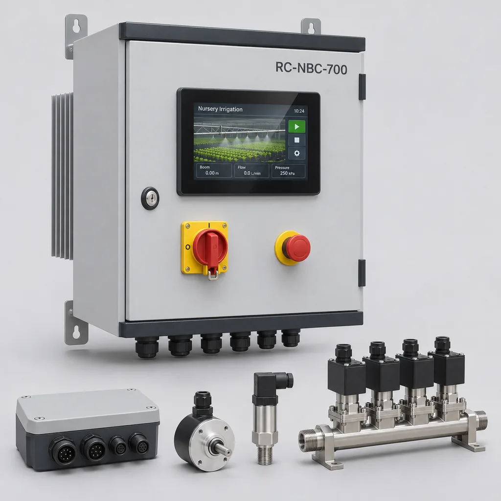
The reference package contains a fixed control cabinet, a sealed moving I/O node, a position encoder and home reference, a flow meter, a boom-side pressure transmitter, and four irrigation section valves. The fixed cabinet contains the local controller, a 7-inch operator interface, a 24 VDC supply, industrial drive interfaces, and an independent machine safety circuit. REDCOAST.LTD develops the acquisition and control boards around the selected sensors and actuators; industrial drives and safety devices are selected as traceable components. Rails, carriage, hose management, nozzles, and structural supports are surveyed for retrofits or specified separately for new installations.
Before watering, the controller checks local automatic-mode authorization, position validity, travel limits, and the water-supply permissive. A recipe defines which sections operate along each stretch of the lane, the travel direction, and the required passes. Low pressure, unexpected flow, or lost motion feedback initiates a configured process stop and records the affected zone. Flow limits are learned during commissioning for each active-section combination, preventing a legitimate partial-width run from being treated as a leak. The standard system monitors aggregate flow; individual nozzle blockage detection requires inspection or additional sensing.
The edge controller performs movement and watering decisions locally. The Web platform distributes approved recipes, stores operating history, and issues maintenance notifications, while the mobile app supports inspection and alarm acknowledgment. Remote requests remain subject to local machine permissions, and a cloud command cannot reset an emergency stop. Each record includes its timestamp, machine identity, recipe revision, delivered volume, and completion status; interrupted jobs remain distinguishable from completed jobs after reconnection.
Connectivity & Power
The reference electrical configuration uses AC 200–240 V, single phase, 50/60 Hz, with a 24 VDC auxiliary supply for electronics and valves. The configured drive range is 0.25–0.75 kW motor output, and the reference connected-load budget is 1.2 kW for the control and motion package. An upstream irrigation pump is a separately sized load. These installations normally have building power, so the package uses a wired mains supply and cable-management system.
Ethernet is the preferred cabinet connection where a nursery network is available; optional 4G LTE provides backhaul when fixed networking is impractical. Isolated RS-485 carries Modbus RTU over an approved flexible cable to field devices, and Modbus TCP provides a documented interface to a site supervisory system. Remote services use TLS-protected connections and individual device credentials. A power failure de-energizes normally closed valves and removes the drive command; power restoration requires the configured local recovery procedure before movement resumes. Hydraulic surge control and stopping behavior are checked against the actual installation.
Protection & Reliability
The reference cabinet has an IP65 enclosure design target, while the moving I/O assembly targets IP67 with correctly mated connectors. The proposed operating envelope is +5 to +40 °C for sheltered nursery service; wet piping must be drained before freezing conditions. Conformal coating, sealed cable entries, condensation management, and separated wet and electrical routing address the humidity associated with irrigation. Drive heat is routed to an external heat sink, and final temperature-rise testing must represent the selected motor, valve duty, and mounting arrangement.
Steel cabinets and brackets use a corrosion-protective galvanized base with a smooth powder-coated finish. More aggressive coastal exposure requires a project-specific coating and fastener specification; no salt-spray duration or unrestricted outdoor service life is implied. The standard installation is sheltered, so exposed wind loads, structural anchorage, and spray drift need separate engineering before outdoor use. Flexible cables, hose supports, filters, seals, and nozzles are service items. The project quotation defines warranty duration, exclusions, replacement-board provision, and service response arrangements.
Application Scenarios
Public tree and landscape nurseries. Municipal growing facilities often share a house between young trees, shrubs, and seasonal bedding plants with different watering needs. Zone recipes let staff change schedules as batches move while retaining a record of each run.
Containerized forest seedling production. Small containers need consistent coverage across dense tray layouts, and delivery conditions at the boom matter more than the pump-room pressure alone. Boom-side pressure monitoring and commissioning catch tests help identify distribution problems before relying on unattended schedules.
Commercial plug and bedding-plant houses. Production blocks are frequently cleared and refilled, leaving temporary empty stretches between crops. Position-based skip zones and independent transverse sections let the watering program follow the current bench layout.
Conservation and research nurseries. Trial blocks need identifiable treatment recipes and records that distinguish intended settings from completed applications. Recipe revisions and measured flow totals provide traceability, while researchers remain responsible for experimental design and plant-response measurements.
Existing boom modernization projects. A sound carriage and rail system may outlast its original electronics or remote control. A surveyed retrofit can replace the control and monitoring package while retaining suitable mechanical assets and documenting the new interfaces.
Case-style Examples
The following are illustrative engineering scenarios, not claims of completed customer installations.
Mixed-crop nursery bay. Consider an 8 m effective spray width and a 60 m planted travel length, divided into six crop blocks. At 24 L/min total flow and 3 m/min steady travel, nominal gross application is 24 ÷ (8 × 3) = 1 L/m² per pass. One uninterrupted pass across the planted length takes 20 minutes and delivers 480 L, excluding lead-in, turns, and parking. This calculation gives the operator a checkable starting recipe; catch tests establish actual collection uniformity and edge behavior.
Public planting-stock facility. A nursery with different crops on the left and right of a shared lane selects four valve sections and an occupancy map. Staff disable sections over cleared benches and assign additional passes only to crop blocks requiring them. The intended operational result is fewer manual controller changes and a clearer watering record; any reduction in water use is measured against the facility's own baseline.
Legacy machine control replacement. An operator has a serviceable 10 m boom with a 0.55 kW motor but an obsolete timer panel. After checking drive compatibility, encoder mounting, rail condition, and stopping requirements, the retrofit adds an eight-section node, pressure sensing, and Ethernet reporting. Acceptance includes verifying direction, zone boundaries, valve timing, and fault recovery on that machine, rather than assuming compatibility from its motor power alone.
Customization & Selection Guide
Start with a dimensioned layout showing rail length, effective spray width, bench positions, aisle crossings, parked position, and hose routing. Four sections suit simpler crop layouts; eight sections provide finer transverse selection where the plumbing can actually isolate those areas. Longitudinal zone boundaries must account for nozzle spray footprint, valve response, acceleration, and deceleration. Encoder setting resolution does not establish watering-edge accuracy.
Match nozzles, operating pressure, flow, and travel speed together. The reference selection range is 2–3 bar at the spray line and 5–60 L/min total measured flow, with nozzle size and active-section combinations chosen to remain inside the selected meter's usable range. The nominal application relationship is D = Q ÷ (W × v), where D is L/m², Q is L/min, W is active effective width in metres, and v is m/min. This is gross applied volume, not plant uptake, and it does not prove uniformity. Commercial reference equipment also combines regulated spray pressure with adjustable travel speed; see the BCC greenhouse boom technical sheet. Programmable inter-zone cycles and multiple valve outputs are established equipment features, as described in the Urbinati IRMO4 specification.
For a cost-focused retrofit, retain inspected mechanical assets and use Ethernet with four sections. For a multi-bay facility, add cellular backhaul where needed and centralize reporting across individually controlled machines. Existing nutrient-water equipment can exchange ready and inhibit signals through a defined interface, but mixing accuracy and chemical compatibility remain properties of that separate equipment. Water-source backflow protection, filtration, drainage, and sanitation are selected for the actual supply and crop process.
Deployment & After-sales
Deployment starts with a mechanical and electrical survey, followed by an approved interface schedule and installation drawing. Install the fixed cabinet outside the direct spray path, route flexible services through the specified carrier, and position pressure sensing at the boom. The project sequence includes bench testing, on-site direction and limit checks, home-reference calibration, dry travel, wet commissioning, and operator training. Procurement should allocate separate milestones for design approval, custom PCB manufacture, enclosure assembly, and acceptance; the delivery schedule is confirmed after the interface and component list are frozen.
Acceptance checks include collected-water distribution, pressure under the least favorable hose position, flow with different section combinations, emergency stops, loss of feedback, and recovery after power or network interruption. Provide wiring diagrams, configuration backups, calibration records, an agreed spare-parts list, and a maintenance schedule with the delivered package. After-sales support can include remote diagnostics, controlled firmware updates, replacement boards, and integrator training. Regular service should inspect filter loading, nozzle condition, cable flex points, hose drag, and rail alignment; the maintenance interval follows water quality and operating hours.
Standards & Compliance
The RC-NBC-700 is a build-to-order product concept with a defined reference specification. The figures below are engineering selection targets for quotation and design, rather than evidence of completed type testing. Contractual ratings, conformity documents, and acceptance criteria must identify the delivered configuration.
Machine risk assessment and risk reduction should follow the applicable framework in ISO 12100:2010. Electrical equipment design should address IEC 60204-1:2016 and its applicable amendments, including the 2021 amendment. Emergency-stop design is addressed by ISO 13850:2015, and safety-related control design by ISO 13849-1:2023. The required safety functions and performance levels come from the machine risk assessment; no SIL or PL rating is claimed for the custom process-control PCB.
Ingress-protection claims require assembly-level verification against IEC 60529, including fitted glands, operator controls, and connectors. Applicable EMC, electrical installation, radio approval, restricted-substance, and machinery conformity requirements are identified for the destination and delivery date. CE marking or other approval documentation is supplied only for the assessed configuration; a component certificate alone does not establish whole-machine conformity.
Why REDCOAST.LTD
REDCOAST.LTD delivers the control hardware, embedded firmware, Web platform, mobile app, and integration documentation as one project. In-house PCB development allows sensor interfaces, valve-driver protection, connector arrangements, acquisition channels, and communications to be engineered around the customer's machine instead of forcing every retrofit into a fixed generic controller.
This capability is particularly useful when older equipment has undocumented wiring, several bays need consistent operating records, or a nursery wants a controlled migration from local scheduling to centralized management. The project scope can include interface reverse engineering, a new board design, prototype verification, and a maintainable replacement strategy, with mechanical and safety responsibilities explicitly assigned.
Contact REDCOAST.LTD with your nursery layout, boom and motor details, available water pressure and flow, and preferred network connection to request a tailored RC-NBC-700 proposal.
Specifications
Boom Motion & Crop Zoning
- Controlled machines per cabinet
- 1 rail-mounted irrigation boom
- Reference effective spray width
- 4–12 m
- Reference travel length
- 20–100 m
- Commissioned watering-speed range
- 1–10; subject to motor gearing and stable nozzle operation m/min
- Compatible drive motor output
- 0.25–0.75; motor and drive matched during survey kW
- Longitudinal recipe zones
- 32 per travel lane zones
- Independent transverse sections
- 4 standard; 8 with expansion sections
- Programmable starts
- 32 per day starts/day
Hydraulics & Measurement
- Spray-line operating pressure
- 2–3 at the boom during watering bar
- Reference supply pressure
- 4–6 at the inlet; confirm dynamic hose and filter losses bar
- Reference water connection
- DN25 / G1; adaptors selected for existing pipework
- Standard flow-meter selection range
- 5–60; every enabled section combination must remain within range L/min
- Pressure transmitter range
- 0–10; 4–20 mA output bar
- Pressure transmitter selection accuracy
- ±0.5% of full scale at reference temperature; calibration required
- Reference nozzle spacing
- 250 or 500; overlap matched to nozzle type and height mm
- Inlet filter nominal opening
- 130; finer filtration where the nozzle supplier requires it µm
Grid Power & Valve Supply
- AC input voltage
- 200–240, single phase V AC
- Supply frequency
- 50/60 Hz
- Reference connected-load budget
- 1.2 maximum for control and motion package; upstream pump excluded kW
- Controls-only standby design budget
- 40 maximum; drive stopped and valves closed W
- Auxiliary DC supply
- 24 VDC, 5 A, 120 W
- Valve coil selection
- 24 VDC, normally closed, maximum 8 W per coil
- Aggregate installed valve-coil budget
- 64 maximum across 8 channels W
Custom Control Hardware & Interfaces
- Local operator display
- 7-inch touch panel
- Analog acquisition
- 4 × 4–20 mA channels; 16-bit conversion
- Discrete process inputs
- 12 × 24 VDC; separate from safety-device circuits
- Position feedback
- 1 incremental A/B encoder input plus home-reference input
- Flow pulse input
- 1 channel, 0–1000 Hz
- Valve-driver current rating
- 0.5 per channel; installed coils limited by aggregate power budget A
- Industrial drive command
- 0–10 V speed reference or Modbus RTU; discrete run and fault signals
- Machine stop architecture
- Dual-channel emergency-stop circuit, monitored safety relay, drive STO or assessed contactor arrangement
Connectivity, Software & Records
- Wired network
- 1 × 10/100 Ethernet Mbit/s
- Serial interfaces
- 2 × isolated RS-485 ports
- Cellular option
- 4G LTE Cat 1 or Cat 4; modem bands selected for destination
- Integration protocols
- Modbus RTU, Modbus TCP, MQTT over TLS, HTTPS
- Telemetry interval
- 1–60, configurable; alarms transmitted on event when connected s
- Offline record-retention target
- 30 at 1-minute status logging plus event records days
- Recipe storage
- 64 recipes with revision identifiers recipes
- Report export
- CSV and JSON; run volume, pressure, recipe, alarms, completion state
Enclosure & Operating Environment
- Fixed cabinet ingress design target
- IP65; assembled configuration requires verification
- Moving I/O enclosure design target
- IP67 with specified mated connectors; assembly verification required
- Reference operating ambient
- +5 to +40; sheltered service and nonfreezing wet circuit °C
- Drained equipment storage range
- -20 to +60 °C
- Internal humidity design envelope
- 10–95; noncondensing inside electrical enclosures % RH
- Reference cabinet dimensions
- 600 × 500 × 250, height × width × depth; external heat sink additional mm
- Steel enclosure finish
- Galvanized corrosion-protection base with smooth matte powder coating, RAL 7035
Capabilities — configurable per project
Specifications are tailored to each project — the options below show what we can support.
Project Delivery
- Control retrofit for an inspected existing boom
- Control package with newly specified rail, carriage and hydraulic equipment
Spray Section Configuration
- 4 independently switched sections
- 8 independently switched sections
- Separate left and right bench groups
Flow Measurement Package
- 5–60 L/min standard flow range
- 1–30 L/min low-flow range for small nozzle groups
Site Connectivity
- Ethernet backhaul
- Ethernet with 4G LTE backup
- 4G LTE primary backhaul
Software Deployment
- Managed Web platform and mobile app
- Customer-hosted server and mobile app
- Integration with an existing nursery supervisory system
Related solution guidance

Environmental Monitoring
Deploy environmental monitoring stations with sensors, solar power, gateways, dashboards, alarms and data integration for city and industrial sites.
Street Lighting Guide
A practical guide to choosing smart street lighting controllers, connectivity, platform features, dimming logic and acceptance tests.
Solar IoT Guide
A design guide for solar-powered outdoor IoT: load calculation, battery autonomy, low-power firmware, telemetry and maintenance planning.
Frequently Asked Questions
What does the RC-NBC-700 irrigation boom system include?
The reference package includes the control cabinet, moving I/O node, position feedback, flow and pressure instrumentation, four valve sections, and integrated Web and mobile software. Eight-section configurations are available. Existing rails, carriage, drive mechanics, hose routing, and nozzles are surveyed for a retrofit; new mechanical equipment is itemized separately in a complete project quotation.
Can the controller upgrade an irrigation boom from another manufacturer?
A retrofit is possible when the existing mechanics, drive, sensor interfaces, and safety arrangement pass the project survey. REDCOAST.LTD can develop custom PCBs, harnesses, and firmware for agreed interfaces. Compatibility is confirmed from wiring diagrams and machine inspection, because motor power or boom width alone cannot establish suitability.
How is irrigation depth calculated on a traveling boom?
Nominal gross application in L/m² equals total active nozzle flow in L/min divided by effective active width in metres and steady travel speed in m/min. For example, 24 L/min across 8 m at 3 m/min gives 1 L/m² per pass, equivalent to 1 mm gross water depth. Nozzle overlap, runoff, acceleration, and edge effects mean commissioning catch tests are still needed; this calculation does not measure plant uptake.
Does the system require solar panels or a dedicated irrigation pump?
The reference package uses AC 200–240 V, single phase, 50/60 Hz from the nursery electrical installation and does not include solar panels. It uses an existing suitable water supply or a separately sized pump. The 1.2 kW reference electrical budget covers the control and motion package only; pump energy and hydraulic capacity are calculated separately.
What happens if the internet connection or mains power fails?
During an internet outage, stored local schedules can continue while the machine remains locally authorized and all operating conditions are healthy; records are buffered for later upload. Mains failure de-energizes the normally closed valves and removes the drive command. Restart follows the commissioned local recovery procedure, including position checks, and remote software cannot reset an emergency stop.
Can the system identify a blocked nozzle or guarantee water savings?
The standard configuration checks aggregate flow and boom-side pressure against the expected active-section combination. It can flag significant deviations, but it cannot reliably identify every individual blocked nozzle. Regular nozzle inspection and collected-water tests remain necessary, and water savings must be measured against the site's own baseline rather than inferred from automation alone.
Which specifications and certifications are confirmed before delivery?
The published figures define the proposed build-to-order reference configuration and its selection limits. The delivered assembly must be checked against agreed electrical, thermal, ingress-protection, hydraulic, and machine-safety requirements. Applicable conformity documents and any claimed safety performance level depend on the final configuration and its validation; custom PCB design alone does not establish certification.