Overview
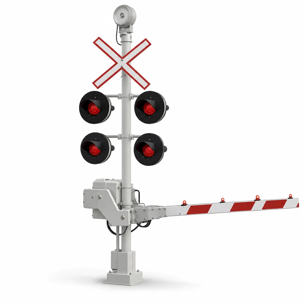
The RC-LX-500 is a complete active warning system for railway level crossings, engineered for rail operators, infrastructure authorities and system integrators who need to upgrade passive or unmanned crossings to automatic protection. Worldwide, tens of thousands of level crossings still rely on static signage alone, and collisions between road vehicles and trains remain one of the deadliest failure points of any rail network. The RC-LX-500 detects an approaching train, activates road-side LED flashing signals and electronic bells with a configurable warning time, lowers half-barrier gates, and optionally scans the crossing zone with 77 GHz radar to confirm it is clear — all while reporting equipment health and every activation event to a central management platform. It is a mains-powered system with battery-backed fail-safe operation, delivered as an end-to-end package: trackside sensors, signal masts, barrier machines, control cabinet, management software and mobile app, from one supplier.
Key Features
- Fail-safe train detection using dual-redundant magnetic wheel sensors (axle-counting principle) with SIL-rated sensor options; train presence, direction and speed are computed at the wayside to trigger warning with a constant, configurable approach time.
- High-visibility road signals: paired 300 mm (12 in) LED flashing light units per mast with ≥300 m daytime visibility, hooded lenses, and self-diagnosing REDCOAST.LTD constant-current driver PCBs that report individual lamp failure.
- Electronic warning bells with 85–110 dB(A) adjustable output and day/night volume profiles for residential areas.
- Half-barrier gate machines with brushless DC drive, adjustable 6–12 s lowering time, boom lights, manual hand-crank release and breakaway boom adapters that prevent structural damage from vehicle strikes.
- Optional 77 GHz FMCW radar obstacle detection covering the danger zone, so a stalled vehicle inside the crossing can hold an alarm output or trigger event recording before the train arrives.
- 2-out-of-2 fail-safe crossing controller built on REDCOAST.LTD's own control and I/O PCBs, with relay-based vital outputs, watchdog supervision and a default-to-warning failure philosophy.
- Battery-backed grid power: the system runs from AC mains and rides through outages on a LiFePO4 bank sized for 8–48 hours of full operation, managed by an in-house charger/UPS power management PCB.
- Full remote monitoring: every activation, lamp status, barrier cycle, battery voltage and door-open event is logged locally (100,000-event recorder) and pushed over 4G/5G or fiber to the LCWS management platform and mobile app.
- Interfaces to existing signalling: dry-contact and serial interfaces allow connection to station interlockings, track circuits or adjacent crossing controllers where required.
Technical Architecture
The system is organised in four layers. At the detection layer, pairs of magnetic wheel sensors are clamped to the rail at calculated strike-in points on each approach. REDCOAST.LTD's sensor signal-conditioning PCB digitises the wheel pulses, filters vibration and interference, and computes axle count, direction and speed. Because strike-in distance is fixed but train speeds vary, the controller supports both fixed-distance and speed-proportional activation logic, keeping the road warning time close to the configured target (typically 25–35 s) instead of penalising road users with excessive closed time for slow trains.
At the control layer, a 2-out-of-2 crossing controller executes the warning sequence: signals and bells start first, the entrance barriers begin lowering after a configurable pre-warning delay (typically 7–10 s), and the crossing remains protected until the axle-counting logic confirms the complete train has cleared the island zone. All vital outputs are relay-supervised; any discrepancy between the two processing channels, a lamp circuit failure or a power anomaly drives the crossing to its safe state and raises a remote alarm. A sealed event recorder stores time-stamped activations, sensor states and barrier positions for incident investigation.
At the warning layer, LED signal drivers regulate lamp current per unit and measure real load, so a failed LED array is detected electrically rather than waiting for a public complaint. The barrier machines use a brushless DC motor with torque monitoring: an obstruction during lowering triggers a configurable raise-and-retry routine. At the management layer, an edge gateway aggregates all diagnostics and streams them over MQTT/TLS to the cloud platform, where operators see live crossing status, receive fault tickets, and export regulatory activation reports.
Connectivity & Power
The RC-LX-500 is designed for grid supply, which is the standard for level crossings on national and industrial rail networks: the control cabinet accepts AC 100–240 V 50/60 Hz and runs the entire crossing on a DC 24/48 V internal bus. Because a level crossing must never go dark during a blackout, an integrated LiFePO4 battery bank — supervised by REDCOAST.LTD's charger and power-management PCB — sustains full warning operation for 8 to 48 hours depending on the configuration ordered. Battery health, charge current and remaining autonomy are reported to the platform. For telemetry, the standard configuration uses industrial 4G/5G with dual SIM; trackside fiber (100Base-FX/1000Base-X) is available where the railway has a lineside backbone, and both can run in parallel with automatic failover. Remote crossings on non-electrified rural lines can be ordered as a wind–solar hybrid variant, but this is a project-specific option rather than the default.
Protection & Reliability
All wayside enclosures are rated IP65 (signal heads IP66), with 304 stainless or hot-dip galvanized steel masts finished in smooth powder coating for long-term corrosion resistance. The electronics operate from -40 to +70 °C with conformal-coated PCBs, and EMC design follows EN 50121-4 for railway signalling apparatus. Mechanical parts — barrier gearboxes, hinges, boom couplings — are specified for a minimum of 500,000 operating cycles, and the LED signal modules for 50,000 h. Salt-spray tested finishes suit coastal corridors; heater and forced-ventilation kits cover arctic and desert deployments. The design philosophy is fail-safe throughout: loss of power beyond battery autonomy, processor disagreement or a broken sensor circuit all result in the crossing presenting its warning state, never a silent failure.
Application Scenarios
- Unmanned rural and regional-line crossings: replace passive crossbuck-only crossings with automatic warning, dramatically reducing collision risk on lines where staffing every crossing is impossible.
- Freight, port and mining branch lines: protect crossings on industrial spurs where shunting movements are frequent and slow; speed-proportional activation avoids long road closures.
- Urban light rail and commuter corridors: high-cycle-rate barrier machines and day/night bell profiles suit dense traffic and noise-sensitive neighbourhoods.
- Crossing modernisation programmes: national safety programmes upgrading hundreds of crossings benefit from a standardised, remotely monitored package with centralised reporting.
- Temporary or construction crossings: rapid-deployment variants protect haul-road crossings over active tracks during infrastructure projects.
- Pedestrian-only crossings: a reduced configuration (signals, bells, optional swing gates, no road barriers) protects footpath crossings near stations and schools.
Case-style Examples
Regional-line safety upgrade programme. A rail authority needed to convert dozens of passive crossings on a 300 km diesel regional line to active protection with minimal civil works. Each site received the RC-LX-500 with wheel-sensor detection, two signal masts, two half-barriers and 4G telemetry, powered from nearby distribution feeds with 24 h battery autonomy. The central platform now gives the authority a single dashboard of activation counts and faults, and lamp failures are dispatched automatically instead of being found by patrol.
Port branch-line crossing with heavy truck traffic. At a container terminal access road crossed by a shunting spur, slow moves previously kept a manually operated gate closed for long periods. The speed-proportional activation logic cut average road closure time significantly while the optional radar obstacle detection watches the danger zone for stalled trailers, holding an output that can be tied into the terminal's shunting radio procedures.
Commuter corridor with noise constraints. A crossing surrounded by housing required full warning performance without night-time noise complaints. The electronic bells were profiled to 95 dB(A) by day and 85 dB(A) at night, LED signals were fitted with louvred hoods to limit light spill into homes, and the operator monitors barrier cycle counts to schedule preventive maintenance before rush-hour failures occur.
Customization & Selection Guide
Choose the configuration by traffic moment (road traffic × train frequency) and regulatory class. Flashing-light-only configurations suit low-traffic rural crossings and footpaths; add half barriers (the most common worldwide) for public road crossings; specify four-quadrant full barriers where regulations demand complete closure. Select approach warning time (20–60 s) and activation logic per your national rulebook; select boom lengths (3–8.5 m) to match carriageway width. Add radar obstacle detection where queuing traffic can back up onto the crossing, and an ANPR camera option where violation evidence is required. For power, standard 8 h battery autonomy suits stable grids; 24–48 h autonomy or the wind–solar hybrid variant suits weak-grid and remote sites. REDCOAST.LTD engineers review each site plan — approach speeds, gradients, road geometry — and deliver a per-site configuration sheet before manufacture.
Deployment & After-sales
The system ships as pre-wired assemblies: masts with signal heads fitted, barrier machines pre-tested with their booms, and a factory-configured control cabinet, so a typical two-mast, two-barrier site is installed on prepared foundations and commissioned in days rather than weeks. Wheel sensors clamp to the rail foot without drilling. REDCOAST.LTD provides site-survey templates, foundation drawings, commissioning checklists and remote engineer support during cutover, plus operator training for the management platform. Standard warranty is 24 months (extendable to 60), with spare-parts kits, firmware updates over the air, and 24/7 remote diagnostics available under support agreements.
Standards & Compliance
The RC-LX-500 is engineered following CENELEC railway application standards: EN 50126 (RAMS lifecycle), EN 50129 (safety-related electronic systems) design principles, EN 50121-4 (EMC for signalling apparatus) and EN 50125-3 (environmental conditions for signalling equipment). SIL-rated wheel-sensor detection options are available where the project safety case requires certified train detection. Road-side warning equipment follows the flash-rate and photometric practices of AREMA C&S Manual guidance and national level-crossing rulebooks; CE and RoHS apply to the electronic assemblies, with IP ratings per IEC 60529. Compliance documentation is compiled per project to support the operator's own approval process.
Why REDCOAST.LTD
REDCOAST.LTD delivers complete smart-infrastructure solutions — hardware, web management platform and mobile app — as one integrated package from one team. What sets the RC-LX-500 apart is that the electronics inside are our own: the wheel-sensor signal-conditioning board, the LED signal driver, the barrier motor controller, the radar front-end and the charger/UPS power-management board are all REDCOAST.LTD-designed PCBs, developed and revised in-house. That means the activation logic, diagnostics, interfaces and even enclosure formats can be adapted to your national rulebook and your legacy signalling — not the other way around. From a single pedestrian crossing to a multi-year crossing modernisation programme, we engineer, manufacture, and support the whole system.
Contact REDCOAST.LTD with your crossing list or site drawings for a per-site configuration proposal and quotation.
Specifications
Train Detection & Activation
- Detection Method
- Dual-redundant magnetic wheel sensors (axle counting)
- Detected Train Speed
- 3-200 km/h
- Approach Warning Time
- 20-60 (configurable) s
- Activation Logic
- Fixed-distance or speed-proportional
- Direction & Speed Discrimination
- Yes, per approach
- Sensor Safety Option
- SIL-rated wheel sensor packages
Road Warning Signals
- Signal Lamp Diameter
- 200 / 300 mm
- Flash Rate
- 45-65 flashes/min
- Daytime Visibility
- ≥300 m
- Lamp Failure Detection
- Per-unit current monitoring
- Electronic Bell Output
- 85-110 (adjustable, day/night profiles) dB(A) @ 1 m
- LED Module Rated Life
- 50,000 h
Barrier Gate Machine
- Boom Length
- 3-8.5 m
- Lowering Time
- 6-12 (adjustable) s
- Raising Time
- 6-10 s
- Drive
- Brushless DC with torque monitoring
- Mechanical Life
- ≥500,000 cycles
- Boom Lights
- 3 LED units, flashing with road signals
- Manual Release
- Hand crank + breakaway boom adapter
Obstacle Detection (Optional)
- Radar Type
- 77 GHz FMCW
- Coverage Zone
- up to 30 × 8 m
- Minimum Detected Object
- 0.5 × 0.5 × 0.5 m
- Detection Latency
- <200 ms
- Evidence Camera Option
- ANPR + video clip per event
Control & Monitoring
- Controller Architecture
- 2-out-of-2 fail-safe, relay-supervised vital outputs
- Event Recorder
- 100,000 events, time-stamped
- Connectivity
- 4G/5G dual-SIM, fiber 100Base-FX/1000Base-X
- Platform Protocol
- MQTT over TLS 1.2/1.3
- External Interfaces
- Dry contacts, RS-485, Ethernet
- Management Software
- Web platform + iOS/Android app
Power (grid with battery backup)
- Input Voltage
- AC 100-240, 50/60 V / Hz
- Internal Bus
- DC 24 / 48 V
- Standby Consumption
- 25-60 W
- Peak Consumption (barriers moving)
- 300-600 W
- Backup Battery
- LiFePO4, 1.2-5.0 kWh
- Backup Autonomy
- 8-48 (full warning operation) h
Environmental & Protection
- Cabinet / Signal Head IP Rating
- IP65 / IP66
- Operating Temperature
- -40 to +70 °C
- EMC
- EN 50121-4
- Environmental Design
- EN 50125-3
- Corrosion Protection
- Hot-dip galvanized + powder coat; salt-spray tested
- Wind Load (masts/booms)
- up to 60 m/s
Capabilities — configurable per project
Specifications are tailored to each project — the options below show what we can support.
Crossing Configuration
- Flashing lights + bells only
- Half-barrier (2 gates)
- Four-quadrant full barrier
- Pedestrian crossing kit
Train Detection
- Magnetic wheel sensors (axle counting)
- SIL-rated certified sensor package
- Interface to existing track circuits/interlocking
Obstacle Detection
- None
- 77 GHz radar
- Radar + ANPR evidence camera
Backup Power
- 8 h battery
- 24 h battery
- 48 h battery
- Wind-solar hybrid (remote lines)
Connectivity
- 4G/5G dual-SIM
- Lineside fiber
- Fiber + cellular failover
Related solution guidance
Traffic Safety
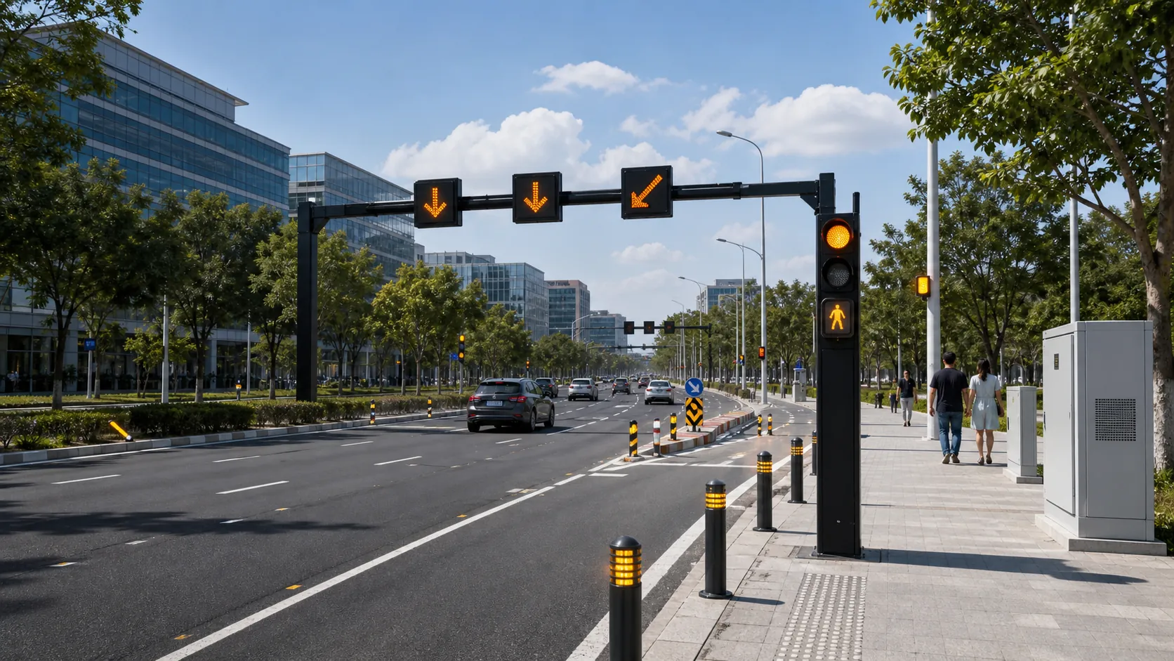
Plan connected traffic safety systems with warning beacons, LED signs, road guidance devices, sensing, control cabinets and monitoring software.
Solar IoT Guide
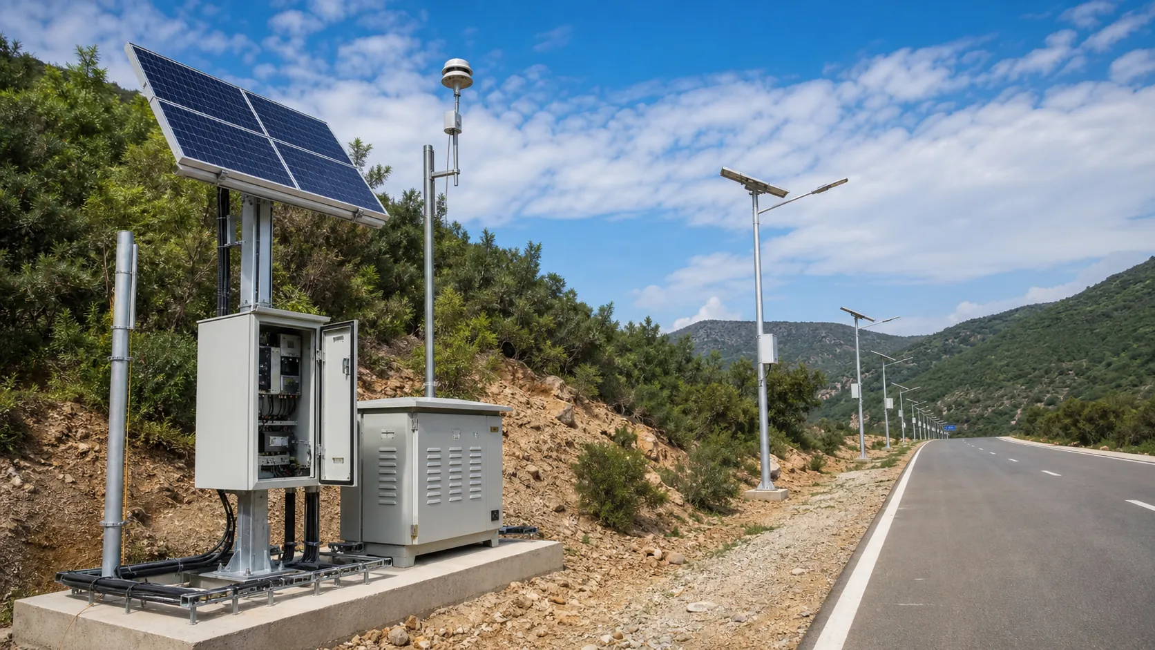
A design guide for solar-powered outdoor IoT: load calculation, battery autonomy, low-power firmware, telemetry and maintenance planning.
Traffic Safety Checklist
Deployment checklist for connected traffic warning signs, beacons, road guidance devices, power, visibility, monitoring and acceptance tests.
Frequently Asked Questions
How does the RC-LX-500 detect an approaching train?
It uses dual-redundant magnetic wheel sensors clamped to the rail foot at calculated strike-in points on each approach. A signal-conditioning PCB counts axles and computes train direction and speed, and the controller activates the warning sequence so road users get a constant, configurable warning time (typically 25–35 s). SIL-rated certified sensor packages are available where the project safety case requires them.
What happens at the crossing during a power outage?
The system runs from AC mains but carries an integrated LiFePO4 battery bank managed by a dedicated charger/UPS board. Depending on configuration it sustains full warning operation — signals, bells and barriers — for 8 to 48 hours. Battery state and remaining autonomy are reported to the management platform so operators can react before autonomy is exhausted.
Is the system fail-safe if a component fails?
Yes. The crossing controller uses a 2-out-of-2 architecture with relay-supervised vital outputs, and the design philosophy is default-to-warning: processor disagreement, a broken sensor circuit or lamp-circuit failure drives the crossing to its protective state and raises a remote alarm, never a silent failure.
Can it detect a vehicle stuck on the crossing?
With the optional 77 GHz FMCW radar module, the danger zone (up to about 30 × 8 m) is scanned continuously. A stalled vehicle or large object holds an alarm output within 200 ms, which can trigger event recording, an ANPR evidence camera, or an interface output to the railway's operational procedures.
How long is the warning time and can it be adjusted for slow freight trains?
Approach warning time is configurable from 20 to 60 seconds per national rulebook. With speed-proportional activation, the controller uses the measured train speed so a slow shunting move does not close the road far earlier than necessary, keeping closure times reasonable at freight and port crossings.
What standards does the system follow?
It is engineered following CENELEC railway standards — EN 50126 RAMS lifecycle, EN 50129 design principles for safety-related electronics, EN 50121-4 EMC and EN 50125-3 environmental conditions — with CE/RoHS for the electronic assemblies and IP65/IP66 enclosures per IEC 60529. Warning-signal practice follows AREMA C&S Manual guidance and national level-crossing rulebooks, and per-project compliance documentation supports the operator's approval process.
Can the RC-LX-500 connect to our existing signalling or interlocking?
Yes. Dry-contact, RS-485 and Ethernet interfaces allow the crossing to exchange status and control with station interlockings, existing track circuits or adjacent crossing controllers. Because REDCOAST.LTD designs the controller PCBs and firmware in-house, project-specific interface logic can be implemented rather than forcing the railway to adapt.
How long does installation take for one crossing?
Equipment ships as pre-wired, factory-tested assemblies: masts with signal heads fitted, barrier machines pre-tested with booms, and a pre-configured control cabinet. On prepared foundations, a typical two-mast, two-barrier site is installed and commissioned in a few days; wheel sensors clamp to the rail foot without drilling.