Overview
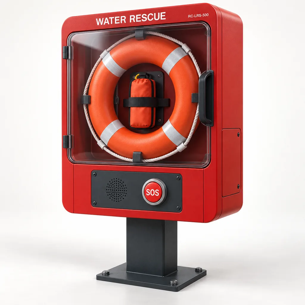
The RC-LRS-500 Smart Lifebuoy Cabinet and Waterfront Rescue Equipment Monitoring Station is a mains-powered solution for municipalities, marina operators, park authorities, campuses, and waterfront property managers. It combines immediately accessible rescue equipment, independent equipment-presence monitoring, a local identification beacon, optional hands-free emergency calling, and a Web platform with a maintenance App. The system addresses a practical operational gap: a missing lifebuoy, removed rescue line, or damaged cabinet can remain unnoticed between inspections, while callers may struggle to describe their exact waterfront location. REDCOAST.LTD delivers the complete station, electronics, software, and project integration, with in-house PCB and board-level development to adapt sensing, communications, and interfaces to the installation.
Key Features
- Separate lifebuoy and line monitoring: Two independent supervised cradle inputs distinguish a missing ring from a missing line pack; cabinet-cover and service-door sensors provide additional context.
- Immediate public access: A mechanical pull-open cover provides access without a key, PIN, payment, smartphone, or electrical release. The electronics compartment has a separate service lock.
- Location-linked SOS calling: An optional SIP audio module calls an agreed monitoring desk and associates the call with the station ID, mapped coordinates, and access-route notes.
- Local event processing: Adjustable 0.2–2 second input qualification, a hardware watchdog, and nonvolatile event storage allow equipment events to be processed locally.
- Actionable maintenance records: The Web dashboard separates equipment presence, inspection status, communications health, and open incidents; the App records photographs, replacements, and technician sign-off.
- Mains-powered visibility: A low-power identification light and event beacon make the station easier to locate after dark, using the existing waterfront electrical infrastructure.
- Serviceable construction: Replaceable sensor brackets, an isolated power module, removable electronics trays, and accessible terminal blocks support repair without replacing the whole cabinet.
- Project-specific hardware: REDCOAST.LTD can develop new monitoring, audio-interface, LED-driver, and power-distribution PCBs to suit the cabinet geometry and the customer's operating procedures.
Technical Architecture
The station comprises a drained rescue-equipment bay, a separately sealed electronics enclosure, and a locked mains service compartment. A standard arrangement holds one nominal 750 mm lifebuoy and one 30 m floating line pack; a 600 mm ring uses a different cradle. Low-force cradle switches monitor the stored items without drilling, tethering, or modifying the buoyant body. Supervised wiring distinguishes a normal contact state from specified cable faults, while separate sensors report the public cover and service door. Presence detection confirms that the designated holder is occupied; it cannot establish rope integrity, buoyancy, or correct packing.
A REDCOAST.LTD controller PCB reads the supervised inputs, enclosure temperature, supply status, and tamper channels. Its firmware assigns events such as equipment removed, equipment returned, service access, and sensor fault, then controls the local beacon and signal relays. An optional audio board combines microphone conditioning, echo control, a Class-D speaker stage, and an industrial SIP processor module. The public SOS button initiates a call independently of the cloud dashboard where the local SIP network remains available. Removal events do not automatically imply theft or a person in the water.
Telemetry travels through Ethernet or an optional LTE modem to the management platform. Each event carries a device identity, sequence number, timestamp quality, and status snapshot; unsent records remain in local storage for later upload. Operators can acknowledge incidents, assign inspections, and retain an audit trail, but an acknowledgement does not clear a physical missing-equipment state. After equipment is returned, a configurable inspection workflow keeps its condition marked as unverified until a technician signs off. Location and condition records follow an established public rescue-equipment management approach, reflected in the water rescue equipment register updated in June 2026.
Connectivity & Power
The reference station uses AC 100–240 V, 50/60 Hz from a permanent waterfront, marina, park, or campus circuit. An isolated 24 V DC supply powers the public-facing sensors, audio electronics, and lighting, with hazardous-voltage terminals confined to the service compartment. Reference consumption is 8–12 W in monitoring mode with lighting and heater off, and 25–35 W during an active call with the event beacon operating. An optional 40 W anti-condensation heater brings the maximum configured input budget to 90 W. It heats the electronics compartment and is not a de-icing system for the rescue bay.
Ethernet is preferred where managed network infrastructure is available. LTE Cat 1 bis provides an alternative data path for sites where network cabling would be expensive; the modem and antenna are selected for local bands and operator approval. SIP speech uses IP data, so low-bandwidth sensor networks are not substituted for the voice path. A 60-second heartbeat with a default three-missed-message rule identifies prolonged loss of contact, although it cannot distinguish every power failure from a network failure.
The station has no solar panel and requires continuous mains supply for electronic functions. Where operational continuity is required, the station and its upstream network can use the site's backed-up electrical circuits. During an unbacked power outage, monitoring, lighting, and calling stop, but the mechanical rescue-equipment access remains usable. Printed station identification and locally approved emergency contact instructions remain visible without electronics.
Protection & Reliability
The electronics enclosure is designed toward IP66 and the public control face toward IK08. These targets apply to the defined assemblies; the drained rescue bay is not represented as a watertight or submersible compartment. A rain hood, downward cable entries, replaceable seals, and a pressure-equalizing membrane reduce water and condensation exposure. Conformal coating protects appropriate PCB surfaces while connectors and service contacts remain accessible.
The proposed outdoor operating range is -20 to +55 °C, subject to qualification of the selected assembly under its actual solar loading. Hot sites can use a light-coloured finish and sunshield, while exposed coastal sites require a coating system selected for the local corrosion environment. Steel cabinets, pedestals, and brackets receive hot-dip galvanizing beneath a smooth powder-coated or fluorocarbon-painted topcoat; visible surfaces are finished coatings. Salt exposure, sand abrasion, wind loading, foundations, and flood elevation are assessed for each site rather than represented by one universal rating.
Maintenance planning covers seals, hinges, sensor alignment, cable glands, audio clarity, and rescue-equipment condition. A five-year electronics service-planning horizon is a design objective, not a demonstrated field-life claim. Warranty duration, replacement stock, software support, and response arrangements are defined in the project quotation.
Application Scenarios
- Urban riverfront promenades: Stations beside public access routes provide visible rescue equipment and a unique location identifier. Missing-item alerts help the maintenance team prioritize replacements along a long waterfront.
- Marinas and recreational harbours: A station near a gangway or shore-side access point connects equipment status with the marina operations desk. Placement accounts for tide, spray, pedestrian clearance, and the approved rescue plan.
- Public parks with lakes or canals: Separate ring and line monitoring reveals incomplete rescue sets that a simple cabinet-door alarm would miss. Inspection records help park teams document condition checks across multiple sites.
- Campuses and business parks with open water: Ethernet-connected stations can share an existing security control room and facilities workflow. The SOS option provides a fixed calling point with a known location for visitors unfamiliar with the grounds.
- Waterfront venues and hospitality properties: Event staff can check equipment presence and overdue inspections before public opening. An event-related removal remains visible until staff inspect and restore the rescue set.
Case-style Examples
The following examples illustrate proposed configurations and intended workflows; they are not claims of completed REDCOAST.LTD installations or measured rescue outcomes.
Riverfront equipment-management upgrade: A municipal operator plans 18 stations along a developed promenade with existing mains circuits. Each station receives a 750 mm ring, a 30 m line pack, independent presence sensors, and LTE telemetry; four staffed gathering points also receive SIP calling. The intended result is a mapped exception list for missing equipment and a documented replacement workflow, supported by continued physical inspections.
Marina help-point consolidation: A marina replaces scattered unmonitored ring holders with six wall-mounted stations near shore-side access routes. Ethernet connects the stations to the operations building, and the optional audio module calls the duty desk using a station-specific identity. Acceptance checks demonstrate that ring removal, line removal, calling, and communications-loss alerts appear as distinct events, enabling staff to respond to the actual condition.
Campus lake inspection workflow: A campus specifies eight stations with existing-network connectivity and local beacon indication. Maintenance staff scan the station ID, inspect the line and ring, and upload a condition photograph through the App. A returned ring restores the presence indication, while the separate inspection status remains pending until the equipment has been checked.
Customization & Selection Guide
Start with the site's water-safety assessment, the required rescue equipment, and the organization responsible for responding. Select the ring, line length, cabinet reach height, and mounting location before choosing the electronics package. Nominal 600 mm and 750 mm ring formats are established housing options, as illustrated by manufacturer lifebuoy-housing specifications; actual ring dimensions and rope-packing clearance must still be checked against the selected cradle.
For a small site with regular staff presence, choose equipment monitoring, Ethernet, and an existing maintenance platform connection. Add LTE where a data cable route is unavailable, or Ethernet/LTE failover where the project needs two paths. Add SIP calling only when an answering organization, escalation procedure, and network service have been agreed. The station does not establish a staffed emergency service by itself.
Specify wall mounting where a suitable structure is available, or a pedestal where visibility and access require an independent station. Coastal exposure may justify a fluorocarbon topcoat and upgraded fasteners; cold, damp sites may justify the electronics heater. REDCOAST.LTD can also adapt the input board to an existing cabinet, retaining the original access arrangement after a mechanical and electrical survey.
Deployment & After-sales
Deployment begins with a location schedule covering power availability, network service, flood level, accessibility, cabinet orientation, and maintenance access. Installation includes foundation or wall-anchor design, protective earthing, circuit protection, cable routing, and testing by competent local installers. No universal station spacing or foundation size is prescribed without the site's risk assessment and structural conditions.
Factory acceptance checks cover sensor removal and restoration, cable-fault reporting, event buffering, restart behaviour, beacon operation, and the configured audio path. Site acceptance repeats these checks with the actual network and monitoring desk, including outage behaviour and confirmation that rescue equipment remains mechanically accessible. Handover includes wiring drawings, station IDs, configuration records, inspection procedures, and administrator training.
Delivery is planned through requirements approval, mechanical and PCB design, prototype review, qualification, and production. New board development and destination-specific testing are scheduled separately from repeat production. Remote diagnostics, firmware maintenance, spare electronics trays, replacement sensors, and platform support can be included in the service agreement.
Standards & Compliance
This page defines a proposed RC-LRS-500 reference configuration for quotation and project engineering. The stated enclosure ratings, operating limits, and power figures are design targets to be verified on the selected build; they are not existing product test certificates.
- Lifebuoy selection: EN 14144:2025 addresses lifebuoy requirements and testing and includes shore equipment near bodies of water within its scope. Specify appropriate supplier documentation for the actual ring; conformity of a lifebuoy does not certify the complete station. See the current BSI standard entry.
- Housing design: ISO 18421:2016 addresses lifebuoy housing construction and dimensions in an inland-navigation context and was confirmed in 2026. Its applicability to a shore installation should be agreed in the project specification. See the ISO standard scope and status.
- Ingress and impact: Qualification should use IEC 60529 for the specified IP rating and IEC 62262 for the specified IK rating, testing the intended enclosure assembly.
- Electrical and communications safety: Assess the audio and communications assembly against the applicable adoption of IEC 62368-1, alongside installation requirements and the selected power supply's documentation.
- Market-specific conformity: The project compliance plan covers applicable EMC, radio, electrical-safety, and restricted-substance requirements, including CE/RED and RoHS documentation where relevant. Radio bands, markings, and test evidence are confirmed for each supplied variant and destination.
Why REDCOAST.LTD
REDCOAST.LTD provides one coordinated solution spanning outdoor hardware, embedded firmware, Web management, mobile maintenance tools, and integration with the customer's operating systems. Its in-house PCB and board-level engineering makes it possible to change sensor supervision, connector placement, audio interfaces, lighting control, and cabinet power distribution when a standard assembly does not fit the project. The team uses suitable industrial modules and documented rescue equipment within an engineered system, with clear responsibility for interfaces, testing, and service access. Buyers receive a defined equipment list and an agreed verification plan rather than relying on broad feature claims.
Contact REDCOAST.LTD with your waterfront layout, rescue-equipment requirements, mains and network availability, and monitoring workflow to request a customized RC-LRS-500 proposal.
Specifications
Rescue Equipment & Mechanical Configuration
- Cabinet dimensions, width × height × depth
- 900 × 1050 × 280 mm
- Reference pedestal-mounted overall height
- 1800 mm
- Nominal lifebuoy outside diameter
- 600 or 750; matched cradle required mm
- Lifebuoy capacity
- 1 ring
- Floating rescue line length
- 30 standard; 20 with selected compact equipment set m
- Public equipment access
- Mechanical pull-open cover; no electrical lock
- Mounting formats
- Wall bracket or floor-anchored pedestal
Equipment Monitoring & Edge Control
- Supervised contact inputs
- 8 total; 4 assigned and 4 spare channels
- Assigned monitored points
- Ring cradle, line-pack cradle, public cover, service door
- Input event qualification
- 0.2–2; configurable, excluding network delay s
- Heartbeat interval
- 30–900; default 60 s
- Offline declaration
- 3–5 missed heartbeats; default 3 messages
- Local event storage
- 100000 records
- Isolated signal relay outputs
- 2; maximum 30 V DC, 1 A resistive per contact channels
Mains Power
- AC input voltage
- 100–240 V AC
- Input frequency
- 50/60 Hz
- Internal isolated supply voltage
- 24 V DC
- Nominal DC power-supply rating
- 120; temperature derating checked per build W
- Monitoring-mode input power
- 8–12; lighting, audio, and heater off W
- Active-call input power
- 25–35; beacon on, heater off W
- Optional electronics anti-condensation heater
- 40 W
- Maximum configured AC input budget
- 90; including heater W
Connectivity & Integration
- Ethernet interface
- 1 × RJ45, 10/100BASE-T
- Optional cellular modem
- 4G LTE Cat 1 bis; destination-specific bands
- Network configurations
- Ethernet; LTE; Ethernet with LTE failover
- Telemetry protocols
- MQTT over TLS 1.2 or later; HTTPS
- Integration interfaces
- HTTPS REST API, JSON event webhooks, CSV export
- Time synchronization
- NTP; unsynchronized records carry a time-quality flag
Optional SOS Audio & Local Indication
- SOS call button
- 1 illuminated physical button button
- Voice interface
- SIP 2.0 over IP; G.711 and G.722 codecs
- Speaker amplifier nominal output
- 10 into 8 ohms W
- Configured call destinations
- 2 sequential SIP destinations destinations
- Event beacon LED power
- 3 W
- Station identification light power
- 3 W
Protection, Environment & Finish
- Electronics enclosure ingress target
- IP66; separate drained rescue bay
- Public control-face impact target
- IK08
- Outdoor operating-temperature target
- -20 to +55; selected assembly qualification required °C
- Electronics humidity range target
- 10–95, non-condensing % RH
- Steel cabinet sheet thickness
- 2.0 mm
- Standard finished surface
- Hot-dip galvanized substrate with smooth matte powder coating
- Colour and coastal finish options
- RAL 3000 red / RAL 7016 anthracite / RAL 9016 white; fluorocarbon topcoat option
Platform & Maintenance Workflow
- Equipment-presence states
- Present, missing, sensor fault, unknown
- Access roles
- Administrator, operator, technician, read-only
- Selectable cloud event retention
- 30, 90, or 365 days
- Operator interfaces
- Web dashboard; Android and iOS maintenance App
- Inspection record fields
- Station ID, condition, photograph, technician, timestamp, replacement record
- Device management
- Remote configuration, signed firmware updates, version inventory
Capabilities — configurable per project
Specifications are tailored to each project — the options below show what we can support.
Communications
- Ethernet on a managed site network
- LTE Cat 1 bis IP connectivity
- Ethernet with LTE failover
Rescue Equipment Package
- 750 mm lifebuoy with 30 m floating line
- 600 mm lifebuoy with 20 m floating line
- Surveyed cradle adaptation for existing approved equipment
Public Interface
- Equipment monitoring and identification lighting
- Monitoring with SIP SOS calling
- SIP calling with site-approved multilingual audio prompts
Installation & Finish
- Wall-mounted coated steel cabinet
- Pedestal-mounted powder-coated station
- Coastal fluorocarbon finish with sunshield
Software Delivery
- Managed cloud Web platform and maintenance App
- Customer-hosted platform deployment
- API integration with an existing facilities or security platform
Related solution guidance

Environmental Monitoring
Deploy environmental monitoring stations with sensors, solar power, gateways, dashboards, alarms and data integration for city and industrial sites.
Ports and Logistics
Outdoor IoT infrastructure for ports, yards and logistics areas: lighting, guidance, safety, solar power, monitoring and maintenance visibility.
Power and Connectivity
How to choose power, battery, solar, NB-IoT, LTE, LoRaWAN, gateways and monitoring strategy for outdoor IoT infrastructure.
Frequently Asked Questions
What does a smart lifebuoy cabinet actually monitor?
The RC-LRS-500 monitors the lifebuoy cradle and rescue-line holder separately, together with the public cover, service door, and electronics health. It reports equipment removal, return, and specified sensor-wiring faults to the platform. Presence monitoring cannot confirm buoyancy, rope condition, correct packing, or whether somebody is in the water, so physical inspections remain necessary.
Can someone take the lifebuoy if the power or network fails?
Yes. The public rescue bay uses mechanical access without an electronic lock, PIN, payment, or App. Electronic monitoring, illumination, and calling require power, while remote alerts and calls also depend on the relevant communications path; a prolonged loss of contact is shown by the platform's heartbeat timeout.
Does this waterfront rescue station need a solar panel?
No. The RC-LRS-500 is specified for developed waterfronts, marinas, parks, and campuses with AC 100–240 V mains infrastructure. Monitoring consumes a reference 8–12 W with lighting, audio, and heater off; the maximum configured input budget is 90 W including the optional heater. Sites requiring operation during outages should include the station and upstream network in their backed-up electrical design.
Can the SOS button call our security desk or public emergency services?
The optional SIP module can call an agreed security desk, marina office, or monitoring centre, with up to two sequential destinations. Connection to public emergency services depends on local service arrangements, routing, and acceptance by the receiving organization. Commissioning verifies call quality, station identification, destination handling, and escalation; the cabinet does not provide a staffed response service.
Which lifebuoy and rope sizes fit the cabinet?
The reference arrangement holds one nominal 750 mm lifebuoy with a 30 m floating line pack; a matched cradle allows a 600 mm ring and selected 20 m line set. The actual buoy dimensions, line packaging, and extraction clearance are checked before manufacture. Equipment type, line length, placement, and documentation are selected through the site's water-safety assessment rather than inferred from cabinet size alone.
Is the complete station certified to EN 14144 or IP66?
EN 14144:2025 concerns lifebuoys, so the selected ring needs its own relevant conformity evidence. IP66 for the electronics enclosure and IK08 for the public control face are proposed station design targets requiring assembly testing. The product configuration does not claim existing complete-station certification, and the drained rescue bay is not rated for submersion.
Can REDCOAST.LTD design the PCB and connect the station to our existing platform?
Yes. REDCOAST.LTD can develop the monitoring controller, supervised-input circuits, audio interfaces, LED drivers, and power-distribution PCBs to the project requirements. Ethernet or LTE telemetry can connect through MQTT, HTTPS APIs, and event webhooks, with managed-cloud or customer-hosted software delivery. The proposal defines hardware development, integration, prototype testing, production scope, and ongoing support.