Overview
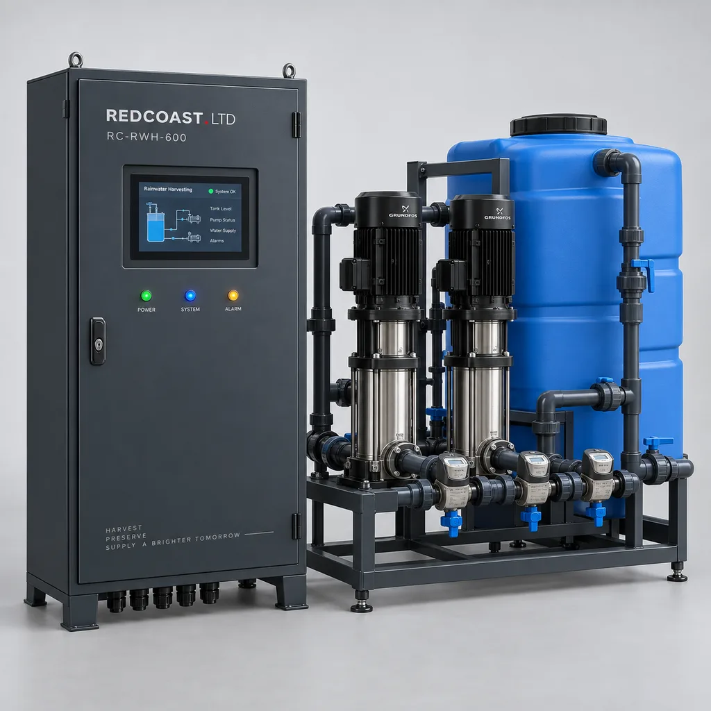
The RC-RWH-600 is a mains-powered rainwater harvesting and non-potable water supply system for campuses, parks, commercial estates, sports facilities, and industrial properties. It combines stored-rainwater management, automatic mains-water replenishment through a physical air gap, pressure-controlled pumping, water metering, and remote operations in one coordinated package. Facility teams can prioritize harvested water while maintaining irrigation availability during dry periods and identifying faults before they become prolonged supply interruptions. REDCOAST.LTD delivers the control hardware, project-specific PCB design, embedded software, Web platform, and mobile app as an integrated solution. The specifications below define a proposed engineered reference configuration; final pump curves, component selections, environmental ratings, and acceptance criteria are confirmed for each order rather than presented as previously certified product performance.
Key Features
- Rainwater-first supply: Automatically transfers available cistern water into a service break tank, with configurable low-level thresholds and hysteresis to prevent repeated source switching.
- Physically separated mains replenishment: Introduces backup mains water through an appropriately approved Type AB air-gap assembly selected for the installation, maintaining separation independently of software operation.
- Duplex pressure-controlled pumping: Uses two booster pumps in duty/standby operation, with automatic alternation, fault changeover, and independent dry-running protection.
- Separate source and delivery metering: Records harvested-water transfer, mains-water replenishment, and delivered non-potable water, making source dependence and abnormal consumption visible.
- Purpose-built control electronics: Incorporates REDCOAST.LTD-designed sensor acquisition, isolated communications, pump-command, valve-driver, and power-supervision PCBs.
- Local operation without internet: Maintains level control, source selection, pressure regulation, and protective interlocks when the external network is unavailable.
- Integration with existing irrigation: Exchanges demand, supply-ready, low-storage, and fault signals with irrigation controllers without requiring replacement of downstream zone equipment.
- Unified maintenance workflow: Presents tank levels, pump hours, alarm history, meter trends, and service records through the local HMI, Web platform, and mobile app.
Technical Architecture
The reference arrangement connects a roof-water collection cistern to a 300 L atmospheric service break tank through a transfer pump. Upstream debris separation and a project-selected collection filter protect storage quality; the control package then supervises cistern level, transfer flow, break-tank level, and independent high-high and low-low switches. When harvested water is available, the transfer pump maintains the break-tank operating band. When the cistern reaches its low threshold, the controller stops transfer and enables mains replenishment through the physical air-gap assembly. A normally closed replenishment valve, an independent high-high cutoff, and a correctly sized passive overflow address different failure modes. The overflow must accommodate the maximum possible simultaneous inflow under fault conditions.
Two variable-speed booster pumps draw from the break tank through flooded suction connections and maintain the selected discharge pressure. The reference duty is 6 m³/h at 3 bar at the package outlet, with one pump carrying the duty and the second reserved for standby. Final selection includes filter losses, suction conditions, pipe resistance, and the manufacturer's pump curve; motor nameplate power alone does not establish hydraulic performance. A small pressure vessel and configurable sleep logic reduce cycling at low demand. Separate low-low contacts inhibit both boosters, while excessive pressure, sustained no-flow operation, and drive faults produce defined stop or changeover actions. Manual operation retains the protective interlocks.
A dedicated embedded controller handles the local state machine, while a separate communications service exchanges telemetry and authorized settings with the platform. Custom PCBs provide protected 4–20 mA inputs, pulse counting, isolated RS-485, 24 V valve control, and watchdog supervision. Industrial pump drives and protective switchgear are selected components within the complete system; REDCOAST.LTD develops the board-level controls and integration around them. Logged records include operating state, sensor validity, source transitions, pump runtime, and configuration changes. Independent meters support water accounting, but source contributions at the outlet are estimates when water mixes in the break tank; reports account for inventory changes and identify overflow or incomplete data rather than equating all transferred rainwater with useful consumption.
Connectivity & Power
The system uses grid electricity because its intended installations already have building or landscape-service power. The controller accepts AC 100–240 V, 50/60 Hz, while the reference hydraulic package uses a separately protected three-phase AC 380–415 V supply with motors and drives selected for the site frequency. Controller consumption is budgeted at 35 W typical and 60 W maximum, excluding motors and the optional 60 W anti-condensation heater. Pump electrical demand is calculated from the selected motor efficiency, drive losses, and actual operating point. The package contains no solar panels or energy-storage battery.
Ethernet is preferred for facilities with an existing network. An optional LTE Cat 1 modem provides telemetry where cabling is inconvenient, subject to local band and carrier compatibility. Modbus RTU connects drives and field devices, Modbus TCP exposes approved operating points to building management systems, and MQTT over TLS supports platform telemetry. Cloud access is not part of the pump-control loop. During a communications interruption, the controller retains settings, continues local operation, buffers records, and uploads them after reconnection. A power interruption stops pumping and closes the mains replenishment valve; restart follows level and fault checks rather than an immediate uncontrolled motor start.
Protection & Reliability
The control enclosure has an IP65 design target with the door closed and approved cable glands installed. Its steel construction uses a hot-dip galvanized corrosion-protection base followed by a smooth matte powder-coated RAL 7016 finish. A sun shield, protected ventilation strategy where required, and condensation control are selected according to the thermal calculation. Coastal installations can specify a suitable fluorocarbon coating system and corrosion-resistant fasteners; coating qualification is agreed for the actual exposure rather than inferred from a generic outdoor designation.
The electronics configuration targets operation from -20 to +55 °C, with the specified heater and enclosure thermal provisions. Water-filled pumps, filters, valves, and tanks require a frost-protected environment maintained between +5 and +40 °C in the reference package. An outdoor cabinet rating does not make exposed hydraulic equipment freeze-proof. Install the equipment above the design flood level, maintain drainage around the foundation, and engineer cabinet anchoring for local wind loads. Surge protection, protective-earth bonding, drive-compatible electrical protection, and segregated signal wiring are included in the electrical design. Replaceable terminal modules, documented PCB revisions, accessible filters, and pump isolation valves support long-term maintenance; service life depends on water quality, cycling, temperature, and maintenance rather than a blanket lifetime claim.
Application Scenarios
Campus landscape irrigation. Roof runoff from teaching buildings or offices feeds an existing cistern, and the RC-RWH-600 supplies a separate irrigation network. Maintenance teams retain their zone schedules while gaining visibility into rainwater availability, backup-water use, and pump condition.
Public parks with nearby service buildings. A visitor center or maintenance building provides a suitable roof catchment, grid power, and access for servicing. The system supplies planting beds and ornamental landscaping while managing dry-season replenishment through a separated mains connection.
Commercial estates and logistics properties. Large roof areas can provide a useful collection source for landscape watering, subject to roof-material and contamination assessment. Separate water meters help estate managers understand whether storage capacity, seasonal rainfall, or irrigation demand limits reuse.
Sports grounds and recreation facilities. The package supplies scheduled turf or planting-zone irrigation from a dedicated non-potable network. Demand handshakes prevent irrigation from starting when storage, replenishment, or pump availability cannot sustain the agreed duty.
Hotels and mixed-use developments. Distributed landscaping often creates a recurring non-potable water demand near existing utility infrastructure. Centralized monitoring allows engineering staff to supervise the rainwater system alongside other building services, with clearly labeled and physically separated pipework.
Case-style Examples
The following examples illustrate selection and operating logic; they are not claims of completed customer projects or measured savings.
Campus cistern retrofit. A campus already has a 30 m³ collection tank and a functioning irrigation controller, but staff manually enable mains top-up when storage becomes low. A proposed configuration adds a 0–5 m cistern level transmitter, the RC-RWH-600 controller, a 300 L air-gap service tank, three water meters, and two 1.5 kW booster pumps selected for 6 m³/h at 3 bar. The intended result is automatic source management and documented backup-water use while retaining the existing irrigation zones. Acceptance testing would demonstrate low-level changeover, standby-pump operation, overflow alarms, and continued control with the network disconnected.
Commercial roof-water assessment. A property has 2,000 m² of suitable roof area and an assumed annual rainfall of 600 mm. Using an illustrative net collection coefficient of 0.8 gives 960 m³ per year of theoretical collected water before storage overflow and seasonal demand mismatch; this is a screening calculation, not a guaranteed saving. A proposed 20 m³ cistern and metered control package would allow actual collection, replenishment, and delivered-water records to be compared through wet and dry periods. Daily rainfall and demand modeling would determine whether a larger tank provides useful additional recovery.
Sports-facility supply continuity. A training ground needs one irrigation block supplied at 6 m³/h and 3 bar, with a standby pump available during servicing. The selected package operates one booster at a time and requires the active replenishment source to sustain the design demand. A 120 L usable operating band in the 300 L service tank provides only about 72 seconds of buffer at that flow, so the design does not treat the break tank as drought storage. Commissioning verifies available mains refill flow and reduces permitted irrigation demand if the source cannot maintain the specified duty.
Customization & Selection Guide
Start with the catchment area, rainfall time series, roof materials, storage geometry, irrigation demand, and available electrical supply. Landscape irrigation is an established priority in commercial and institutional water management, as described in EPA WaterSense guidance. Tank capacity should follow a water-balance model rather than roof area alone. Collection filters, first-flush arrangements where needed, and treatment requirements depend on the catchment and the intended exposure to reused water.
For an existing mechanical installation, select the controls-and-instrumentation package and retain suitable pumps, tanks, and pipework after inspection. For a new installation, select the complete hydraulic package with air-gap assembly, transfer pump, duplex boosters, filtration, meters, and commissioning support. Automatic replenishment and building-management integration are established commercial approaches, illustrated by the Wilo RainSystem AF 400; its published ratings are a market reference, not performance certification for this product.
Specify the required flow and pressure at a named delivery boundary, including the most demanding irrigation zone and elevation change. The reference 100 µm downstream filter protects equipment but does not disinfect water. Any public-contact spray use, toilet-flushing extension, or other additional end use needs its own water-quality assessment and treatment specification. This package does not turn rainwater into drinking water and is not a sewage or greywater treatment plant. Optional treatment-ready I/O can inhibit supply on a treatment fault, but electrical integration does not establish treatment efficacy.
Deployment & After-sales
Deployment begins with a hydraulic schematic, I/O schedule, cause-and-effect matrix, network plan, and responsibility schedule covering collection works, tanks, drainage, electrical feeders, and downstream pipework. The control cabinet mounts on a wall or plinth, with motor drives installed in a separately sized assembly when the full hydraulic package is supplied. Provide safe access to the air gap, overflow, filters, isolation valves, and tank sensors. Site-specific pipe labeling and cross-connection checks are essential before water service begins.
Factory acceptance testing covers sensor simulation, relay and valve outputs, pump sequencing, invalid-sensor behavior, alarm delivery, power recovery, and communications loss. Site acceptance adds measured flow and pressure, independent float operation, replenishment capacity, overflow drainage, meter checks, and checks of all downstream connections. Procurement planning should allow approximately 8–12 weeks after design approval for a reference package using available components, with additional time for new PCB revisions, special switchgear, or third-party testing; the purchase contract establishes the committed schedule.
Delivery documentation includes wiring diagrams, hydraulic drawings, register maps, configuration backups, maintenance procedures, and an agreed spare-parts list. Remote commissioning support, operator training, firmware maintenance, and regional onsite support can be defined in the service scope. A 24-month equipment warranty can be specified in the supply agreement, with clear commencement terms and treatment of consumables, freeze damage, and installation responsibilities.
Standards & Compliance
Rainwater-system design should be assessed against applicable local plumbing and non-potable water requirements. EN 16941-1:2024 provides a relevant framework for on-site rainwater systems. Potable-water separation requires a documented backflow risk assessment and a suitable protective assembly; the EN 1717:2025+A1:2026 standard listing identifies the current European backflow-protection framework. An approved component must retain its required installation geometry and unobstructed overflow arrangement when integrated.
Electrical enclosure protection is specified using IEC 60529. Low-voltage controlgear assemblies are assessed using IEC 61439-1 together with the applicable assembly-specific part. EMC testing, electrical safety, radio approvals, and material restrictions are selected for the equipment and installation environment. Where CE marking or other market conformity documentation is required, it applies to the final supplied configuration and supporting assessment. This proposed product package does not claim existing CE, WRAS, UL, IP test certification, or universal regulatory approval.
Why REDCOAST.LTD
REDCOAST.LTD provides an integrated water-management solution spanning field hardware, local automation, the Web platform, and the mobile app. Its ability to develop new PCBs and board-level hardware allows sensor interfaces, isolation, valve outputs, cabinet dimensions, and control behavior to match the project instead of forcing every installation into a fixed controller format. The same delivery team can coordinate hydraulic interfaces, embedded logic, dashboards, and maintenance workflows, making responsibility for the complete operating sequence clear.
Send REDCOAST.LTD your catchment area, storage details, required irrigation flow and pressure, electrical supply, and integration requirements to request a customized RC-RWH-600 proposal.
Specifications
Hydraulic Reference Configuration
- Design Delivery Flow
- 6 at the specified outlet pressure; one duty booster m³/h
- Design Outlet Pressure
- 3.0 at 6 m³/h; final pump selection includes internal losses bar
- Booster Pump Arrangement
- 2 × 1.5 kW motor shaft rating; duty/standby; individual variable-speed drives
- Reference Transfer Pump
- 0.75 kW motor shaft rating; selection duty 8 m³/h at 10 m total head
- Service Break Tank
- 300 nominal; 120 reference usable operating band; Type AB air-gap assembly L
- External Collection Cistern Options
- 5, 20, 50, 100, or 200; selected by water-balance calculation; separate civil supply m³
- Pressurized Manifold Design Rating
- PN10; DN40 reference discharge connection
- Reference Downstream Filter
- 100 nominal; replaceable or washable element; no disinfection function µm
Grid Power
- Controller Input
- AC 100–240 V
- Controller Supply Frequency
- 50/60 Hz
- Controller Power Budget
- 35 typical; 60 maximum; excluding heater and motors W
- Reference Motor Feeder
- Three-phase AC 380–415; 50 or 60 Hz with matching motors and drives V
- Installed Motor Shaft Rating
- 3.75 total; 2.25 maximum commanded concurrently in duty/standby mode kW
- Optional Cabinet Heater
- 60; thermostatically controlled W
- Field Control Supply
- DC 24; 2 A rated; aggregate loading limited by the controller power budget
Instrumentation
- Collection Cistern Level Transmitter
- 0–5 m water column; 4–20 mA; selected accuracy ±0.5% full scale
- Service Tank Level Transmitter
- 0–2 m water column; 4–20 mA; selected accuracy ±0.5% full scale
- Discharge Pressure Transmitter
- 0–10 bar; 4–20 mA; selected accuracy ±0.5% full scale
- Water Meter Channels
- 3: rainwater transfer, mains replenishment, and non-potable delivery
- Reference Meter Performance
- 2–10 m³/h calibrated range; procurement accuracy target ±1% of reading
- Independent Level Contacts
- 3: cistern low-low, service tank low-low, and service tank high-high
- Additional Fault Contacts
- 2: overflow detection and plant-area leak detection
Control Hardware
- Analog Inputs
- 8 × 4–20 mA; 16-bit conversion; galvanically isolated field interface
- Digital Inputs
- 16 × 24 V; including 4 pulse-capable channels up to 1 kHz
- Relay Outputs
- 12 dry contacts; 2 A at 30 V DC resistive; interposing relays for larger loads
- Valve Driver Outputs
- 2 × 24 V DC; 0.5 A per channel; protected low-side outputs
- Analog Outputs
- 4 × 4–20 mA
- Local HMI
- 7-inch; 800 × 480 pixels; English interface
- Local Scan and Logging
- 100 ms control scan target; 1 s acquisition; 60 s routine records plus event records
- Pressure Setpoint Range
- 2.0–4.0; actual flow at each setpoint limited by the approved pump curve bar
Connectivity and Software
- Ethernet
- 1 × 10/100BASE-T; RJ45 inside sealed cabinet
- Serial Interfaces
- 2 × isolated RS-485; 9,600–115,200 bit/s
- Field and BMS Protocols
- Modbus RTU; Modbus TCP
- Platform Transport
- MQTT over TLS 1.2 or 1.3; HTTPS configuration interface
- Optional Cellular Connection
- LTE Cat 1; single SIM; module bands selected for the deployment
- Local Telemetry Buffer
- Minimum 30 days for 32 points recorded every 60 seconds
- Operating Interfaces
- Local HMI; browser-based Web platform; Android and iOS mobile app
- Access Roles
- 3: viewer, operator, and administrator; configuration audit trail
Environmental and Mechanical Design
- Control Enclosure Protection Target
- IP65; closed door and installed glands; final assembly verification required
- Controller Ambient Temperature Target
- -20 to +55 with specified heater and thermal provisions °C
- Hydraulic Installation Ambient
- +5 to +40; frost-protected plant space °C
- Reference Water Temperature
- +5 to +35 °C
- Relative Humidity
- 5–95; non-condensing inside the electrical enclosure % RH
- Reference Controller Cabinet Dimensions
- 800 × 600 × 300; height × width × depth; motor drive assembly separate mm
- Cabinet Construction
- 1.5 mm steel; hot-dip galvanized corrosion-protection base; smooth matte powder-coated RAL 7016 finish
- Reference Installation Altitude
- 0–2,000; above 2,000 requires drive, insulation, and cooling reassessment m
Capabilities — configurable per project
Specifications are tailored to each project — the options below show what we can support.
Delivery Scope
- Controller, sensors, and metering for an existing hydraulic installation
- Complete transfer, air-gap replenishment, and duplex booster package
- Multi-building supervisory platform connecting 2–16 local systems
Site Electrical Supply
- Three-phase 380–415 V, 50 Hz package
- Three-phase 380–415 V, 60 Hz package
- Three-phase 208–240 V, 60 Hz package with revised motors and switchgear
- Three-phase 460 V, 60 Hz package with revised motors and switchgear
Communications and Hosting
- Ethernet with hosted Web platform
- Ethernet with customer-hosted platform
- LTE Cat 1 telemetry with hosted platform
- Local HMI and BMS integration without cloud access
Hydraulic Integration
- Existing underground cistern with a submersible transfer pump
- Above-ground cistern with flooded-suction transfer
- Treatment-ready interlocks for a separately specified disinfection package
- Additional metered non-potable branch with revised hydraulic sizing
Environmental Package
- Sheltered plant-room installation
- Outdoor shaded control cabinet with frost-protected hydraulics
- Coastal coating system with corrosion-resistant fasteners
- Cold-climate heated plant enclosure with separately sized thermal equipment
Related solution guidance
Environmental Monitoring
Deploy environmental monitoring stations with sensors, solar power, gateways, dashboards, alarms and data integration for city and industrial sites.
Campuses
Campus IoT for lighting, parking, safety, smart poles, environmental data and facility maintenance workflows.
Street Lighting Guide
A practical guide to choosing smart street lighting controllers, connectivity, platform features, dimming logic and acceptance tests.
Frequently Asked Questions
How is this different from a smart irrigation controller?
The RC-RWH-600 manages the water source, storage levels, mains replenishment, booster pumps, and supply metering upstream of the irrigation zones. A conventional irrigation controller decides which zones run and when. The two exchange demand and supply-ready signals so an existing irrigation installation can be retained.
What happens when the rainwater tank is empty?
A low-level condition stops the rainwater transfer pump and enables mains-water replenishment into the service break tank through a physical air gap. Booster operation continues only while the break tank has sufficient water and the active supply can sustain demand. If both sources are unavailable or replenishment is inadequate, the low-low interlock stops pumping and generates an alarm.
Can a solenoid valve or check valve alone protect the drinking-water supply?
Neither is the physical separation specified for this reference design. Mains replenishment passes through a suitable approved Type AB air-gap assembly, selected and installed according to the local backflow risk assessment and plumbing requirements. Its inlet geometry and overflow must remain unobstructed; software monitoring supplements that protection.
Does the system make harvested rainwater safe to drink?
No. The reference package supplies a dedicated non-potable network, and its 100 µm filter does not provide disinfection. Treatment and monitoring must be specified for the catchment and intended end use, especially where people could contact spray or aerosols.
How much mains water can a commercial rainwater system save?
The useful substitution depends on rainfall timing, catchment yield, storage capacity, demand, overflow, and treatment losses. For screening, a 2,000 m² roof receiving 600 mm of annual rain with an assumed net collection coefficient of 0.8 yields 960 m³ before storage and demand mismatch. Actual avoided mains consumption requires operational metering and a defined comparison baseline; this product does not promise a fixed saving percentage.
Will it continue working without internet or electricity?
Without internet, the local controller continues source selection, level control, pressure regulation, and protective interlocks while buffering records. Without electricity, pumps stop and the normally closed mains replenishment valve closes. The reference product has no battery backup, so continuity during a power outage requires a separately engineered facility backup supply.
Can the cabinet and pumps operate outdoors in freezing weather?
The control electronics target -20 to +55 °C with the specified enclosure provisions, but the reference hydraulic equipment requires a frost-protected +5 to +40 °C environment. Outdoor IP protection does not prevent stored water, valves, or filters from freezing. Cold-climate projects need a heated plant enclosure, suitable pipe protection, and an agreed shutdown or drain-down strategy.
What does REDCOAST.LTD develop in-house, and what information is needed for selection?
REDCOAST.LTD develops project-specific control PCBs, sensor interfaces, valve drivers, embedded logic, and the associated Web platform and mobile app. Selected pumps, drives, meters, and protective assemblies are engineered into the complete package. Provide catchment and tank details, required flow and pressure, pipe elevations, water-use requirements, electrical supply, and BMS protocols so the hydraulic and control design can be finalized.