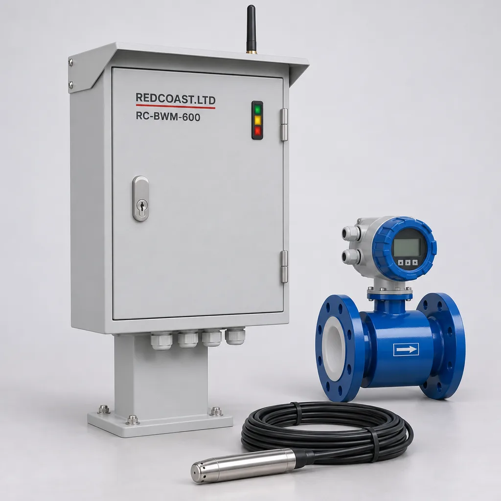
Overview
The RC-BWM-600 is a mains-powered irrigation borehole monitoring station that combines groundwater level measurement, abstraction metering and pump operating status in one managed system. REDCOAST.LTD supplies the outdoor control cabinet, project-selected instruments, edge software, Web platform and mobile App for irrigation operators, municipalities, landscape managers and system integrators. The station helps operators identify excessive drawdown, delayed recovery, unexpected pumping and approaching water-allocation limits before these conditions disrupt irrigation schedules. It is intended for electrically supplied production wells, including farm pump houses, sports facilities and campus irrigation sources, with connections to the existing pump starter or variable-frequency drive.
Key Features
- Water level linked to pump operation: Record depth to water alongside start and stop events, discharge flow and delivery pressure, making pumping and recovery periods easier to interpret.
- Local low-water interlock: A configurable pump-permissive output responds to validated level thresholds locally, with hysteresis, restart lockout and sensor-fault handling.
- Measured abstraction records: Read an existing pulse or Modbus meter, or specify a new electromagnetic meter, to maintain daily, monthly and seasonal volume records.
- Recovery tracking: Compare water-level recovery after shutdown with previous cycles under similar pumping conditions, supporting maintenance investigation and irrigation scheduling.
- Custom board-level hardware: REDCOAST.LTD develops the acquisition, isolated communications, relay-interface and power-monitoring PCBs to match the selected instruments and pump cabinet.
- Operation during network outages: Local supervision and timestamped logging continue while the station remains powered; queued records upload when the connection returns.
- Accountable remote access: Separate viewing, operating and configuration permissions, with event histories for parameter changes, alarm acknowledgements and remote commands.
- Serviceable outdoor construction: A coated steel cabinet, replaceable surge modules, pluggable low-voltage terminals and an accessible probe termination support field maintenance.
Technical Architecture
The reference configuration serves one production well. A vented hydrostatic probe measures pressure below the water surface; a wellhead pressure transmitter, electromagnetic flowmeter and pump run/fault contacts complete the operating picture. REDCOAST.LTD's custom acquisition PCB provides four 4–20 mA inputs, pulse counting and isolated RS485 interfaces. A supervisory controller handles interlocks independently of the gateway's cloud connection. The quoted configuration fixes instrument models, PCB revision, firmware functions and acceptance tests; the specifications below are proposed procurement values, not a declaration of completed prototype testing.
Water depth is calculated from the surveyed probe suspension depth minus the measured water column above the probe, using the configured density correction. Drawdown is the increase in depth to water relative to a recorded pre-pumping reference; that reference is labelled as such until adequate recovery supports calling it a static level. The probe must remain submerged at the low-water trip point and must not exceed its pressure range at the highest expected water level. Cable suspension, datum uncertainty, temperature, density and electronic acquisition error all contribute to system uncertainty; display resolution does not establish measurement accuracy.
The edge controller evaluates signal validity, low-water thresholds, pump feedback and configured abstraction limits before issuing a run permissive. In interlock mode, loss of controller power or an invalid critical sensor de-energizes the normally open permissive contact; the existing starter or drive must be wired to respond to that contact. The system verifies stop feedback and flags a failed stop, while existing motor overload and independent dry-running protection remain active. Remote commands cannot override local trips, and automatic restart is disabled by default. The gateway sends measurements, quality flags and events to the Web platform and App for trends, reports and maintenance follow-up.
Connectivity & Power
The station uses a dedicated AC 100–240 V, 50/60 Hz auxiliary supply from the pump-house or site distribution board. An isolated 24 V DC, 60 W supply powers the controller and selected low-voltage instruments; electronics and two loop-powered probes are budgeted at 12 W typical and 25 W maximum, with a separate 15 W allowance for external instrumentation. The borehole motor retains its own correctly rated feeder and starter or drive. Neither motor current nor motor power passes through the monitoring PCB, and this configuration requires no solar equipment.
Ethernet is preferred where a managed site network is available; a project-selected LTE Cat 1 or Cat 4 modem provides telemetry at dispersed electrically supplied wells. Modem bands, antenna placement, operator coverage and SIM arrangements are checked for each installation. RS485 Modbus RTU connects local meters and drives, while MQTT over TLS or HTTPS carries upstream data. The default upload period is five minutes, with immediate alarm transmission attempts when connectivity exists. During a network outage, local rules and logging continue; during a mains outage, recording stops and the platform reports a missed heartbeat rather than claiming a live field measurement.
Protection & Reliability
The cabinet design targets IP66 after assembly, including the selected glands, antenna feedthroughs and door seals. Its 600 × 400 × 250 mm reference enclosure uses hot-dip-galvanized steel beneath a smooth matte RAL 7035 powder-coated finish, with a separate sun shield where exposed. The proposed outdoor operating range is -20 to +55 °C in shaded conditions, subject to final assembly thermal testing; probe water must remain within 0 to +40 °C and unfrozen. Sealed construction limits dust ingress, while coastal sites require a specified coating system, compatible fasteners and inspection schedule rather than an assumed universal salt-spray lifetime.
Install the cabinet above the site flood level and separate instrument cables from motor and drive cables. Coordinated mains and signal surge protection, protective bonding and shield termination are part of the installation design; these measures do not constitute immunity to a direct lightning strike. Probe IP68 selection must include the supplier's permitted continuous immersion depth and cable construction. Wall brackets or pedestal anchors are checked against local wind loads. Replaceable boards and instruments support long-term servicing, while warranty duration, spare-parts support and inspection intervals are defined in the project quotation rather than inferred from component life claims.
Application Scenarios
Farm irrigation production wells. Install the station beside an existing electrically driven borehole serving drip, sprinkler or pivot irrigation. Combining drawdown, flow and runtime helps the operator separate a restricted water source from a delivery-system problem and adjust irrigation windows using measured conditions.
Municipal parks and sports facilities. Monitor a permitted groundwater source that fills an irrigation storage tank before scheduled watering. Source-level supervision can suspend abstraction while the landscape controller continues to manage available stored water.
Golf course irrigation supplies. Track individual wells feeding a common irrigation reservoir, using one station per well. Operators can compare recovery histories and abstraction totals before deciding which source to operate next.
Campus and industrial-estate landscaping. Connect the borehole station to the site's Ethernet network and existing facilities dashboard. Maintenance teams receive the same event context as irrigation contractors, reducing confusion about whether a stoppage came from low groundwater, a pump fault or an allocation limit.
Irrigation cooperatives and multi-well estates. Consolidate meter totals and level trends from geographically separated, grid-connected pumping sites. Site permissions and downloadable records support internal water accounting without implying that a software total is automatically an approved billing measurement.
Case-style Examples
The following are illustrative configurations, not reported customer installations or measured savings.
Seasonal drawdown at an irrigation well. A hypothetical site has a pre-pumping water depth of 20 m, a probe suspended 65 m below the reference point and a pump intake at 80 m. A 0–50 m water-column probe would read approximately 45 m of head before pumping; a candidate stop depth of 55 m would leave approximately 10 m of water above the probe and 25 m above the intake. Those levels require confirmation against the well test and pump manufacturer's minimum-submergence requirement. With a DN100 meter and local interlock, the proposed result is a traceable low-water stop and recovery record, not a guaranteed increase in aquifer yield.
A campus well with an existing meter. A campus wants remote visibility without replacing a serviceable borehole pump or its approved volume meter. The station reads the meter's isolated pulse output, adds a water-level probe and uses Ethernet to connect to the facilities platform, beginning in monitoring-only mode. After observed operation and an agreed cause-and-effect test, the owner can enable the pump-permissive connection; the intended result is coordinated source supervision with a clear record of why pumping was interrupted.
Customization & Selection Guide
Start with well construction records, pump intake depth, seasonal water levels, pumping-test results, available probe clearance and the electrical drawing. Choose pressure range from the maximum water column above the installed probe, not from total borehole depth; choose cable length from the actual suspension depth and routing. A 50 m range sensor with ±0.10% full-scale reference accuracy contributes ±0.05 m before other errors, while a ±0.25% full-scale temperature error band corresponds to ±0.125 m. Manufacturer specifications such as the KELLER Series 26X data illustrate why these conditions must remain separate. A vented installation needs a dry atmospheric reference; an absolute-pressure alternative requires synchronized barometric compensation.
For an economical retrofit, retain a suitable existing meter and begin with level, flow and pump-status monitoring. For a new metering section, the proposed DN50–DN200 electromagnetic options cover different flows; at 0.5–3 m/s, a nominal 100 mm internal diameter corresponds to approximately 14–85 m³/h. Confirm actual bore, conductivity, pressure rating, full-pipe operation and installation lengths against the selected meter. Manufacturers offer differing hydraulic requirements, including specialized short-run designs such as KROHNE WATERFLUX; their conditions cannot be transferred to every meter. Sites requiring regulatory reporting should select the accepted instrument and data format before ordering the cabinet.
Deployment & After-sales
Survey the wellhead, establish a permanent measurement datum and confirm a clear probe path that avoids the pump, rising main and cable abrasion. A well contractor installs the suspension and sanitary cable entry, and an electrician connects the auxiliary supply, earth and pump interface. Commissioning includes manual water-level comparison, meter scaling, pump feedback verification, simulated low-water and sensor-fault conditions, a network interruption and a controlled power cycle. Interlock operation is enabled only after the actual starter or drive responds correctly in the witnessed test.
Delivery is organized around requirements freeze, approved drawings, PCB and firmware preparation, cabinet assembly, factory acceptance and site commissioning. Existing platform configurations can follow a shorter procurement path; new PCB layouts, unusual instruments or additional qualification tests require a separately agreed schedule. The handover package can include wiring diagrams, I/O mapping, configuration backups, calibration records, acceptance results and operator training. After-sales support covers remote diagnostics, replacement-board configuration, firmware maintenance and agreed spare holdings. Probe cleaning, vent desiccant checks and periodic reference measurements are planned around site fouling and service conditions.
Standards & Compliance
The project compliance plan distinguishes enclosure tests, electrical safety, measurement traceability and local radio requirements. No certification logo or completed test result is claimed for this proposed configuration.
- Enclosure protection: IEC 60529, consolidated Edition 2.2, provides the IP classification framework. The assembled cabinet's IP66 target and each probe's immersion conditions require their own evidence.
- Electrical safety and EMC: IEC 61010-1 with Amendment 1 is a relevant safety reference for measurement and control equipment; IEC 61326-1:2020 provides the corresponding general EMC requirements. The final assessment identifies applicable particular standards, supply conditions and installed radio equipment.
- Field reference measurements: ISO 21413:2005, confirmed in 2025, addresses manual well-level measurement and reference points. It can inform commissioning comparisons but explicitly does not certify automated recording methods.
- Meter acceptance: Where an authority requires an approved meter, confirm the accepted type, flow range and installation conditions. ISO 4064-1:2024 concerns water meters within its stated potable-water scope; it is not a blanket certification for every raw-groundwater installation or the complete station.
Abstraction permissions, reporting intervals and authorized operating limits remain specific to the installation. The station stores configured limits and supporting measurements; sustainable yield and permitted extraction require the responsible authority and qualified groundwater assessment.
Why REDCOAST.LTD
REDCOAST.LTD delivers the monitoring hardware, edge logic, Web platform and mobile App as a coordinated solution, with custom PCB and board-level design supporting the complete system. The team can change sensor excitation, isolation, connector arrangements, relay interfaces and communications hardware to fit the customer's well instruments and existing electrical infrastructure. Software can then present the same agreed signal names, alarm causes and operating permissions across the cabinet, platform and App. This approach gives operators a defined path from site requirements to a serviceable product, with engineering evidence and project acceptance tied to the configuration actually supplied.
Send REDCOAST.LTD your well depths, pump details, meter interfaces and operating requirements to request a tailored RC-BWM-600 configuration and quotation.
Specifications
Groundwater and Pressure Measurement
- Production wells per station
- 1 well
- Hydrostatic probe measuring ranges
- 0–20 / 0–50 / 0–100; select by maximum submerged head mH2O
- Level probe reference accuracy
- ±0.10 at 20–25 °C; sensor only % FS
- Level probe total error band
- ±0.25 over 0–40 °C; sensor only % FS
- Probe cable lengths
- 50 / 100 / 150 / 200; suspension depth and head range selected separately m
- Wellhead pressure range
- 0–10 or 0–16 bar
- Wellhead transmitter accuracy
- ±0.5 at 20–25 °C % FS
- Local measurement interval
- 1; reference analog-input configuration s
Flow Metering
- Optional electromagnetic meter sizes
- DN50 / DN80 / DN100 / DN150 / DN200
- Reference meter pressure rating
- PN16; pressure and temperature derating checked for selected assembly
- Meter procurement accuracy requirement
- ±0.5 of reading at 0.5–5 m/s under supplier reference conditions %
- Minimum water conductivity
- 20; selected meter must meet this requirement µS/cm
- Nominal DN100 planning flow
- 14–85 at 0.5–3 m/s for a 100 mm internal diameter m³/h
- Meter interfaces
- Isolated pulse output or RS485 Modbus RTU
- Straight-pipe planning allowance
- 10D upstream / 5D downstream; final layout follows selected meter
Acquisition and Pump Interface
- Analog inputs
- 4 × 4–20 mA; 24-bit ADC; ADC resolution is not system accuracy
- Digital status inputs
- 6 × 24 V DC; pump run, fault, local mode and auxiliary states
- Pulse inputs
- 2 × isolated counters, 0–100 Hz
- Relay outputs
- 4 dry contacts, maximum 30 V DC / 1 A resistive; external interface for inductive loads
- RS485 ports
- 2 isolated ports, Modbus RTU, 9600–115200 bit/s
- Low-water validation delay
- 2–60; commissioned from pump and well response s
- Recovery hysteresis
- 0.5–10; greater than assessed measurement uncertainty m
- Restart lockout
- 5–120; automatic restart disabled by default min
Grid Power
- Auxiliary supply input
- AC 100–240 V
- Supply frequency
- 50 / 60 Hz
- Internal instrument supply
- 24 V DC, 2.5 A rated
- Installed DC power-supply rating
- 60 W
- Electronics DC load, including two loop-powered probes
- 12 typical / 25 maximum; excludes external meter and pump W
- Additional external instrument allowance
- 15 maximum within the 60 W DC budget W
- Pump power circuit
- Separate existing feeder and starter/VFD; PCB relays carry control signals only
Communications and Data
- Ethernet
- 1 × 10/100BASE-T
- Cellular option
- LTE Cat 1 or Cat 4 modem; market-specific bands and approvals
- Upstream protocols
- MQTT over TLS 1.2/1.3; HTTPS
- Routine upload interval
- 1–60; default 5 min
- Local logging interval
- 1–3600; default 60 s
- Local storage capacity
- 512 MB; minimum 180 days at 60 s with 16 numeric values per record
- Operational records
- Timestamped levels, flow, cumulative volume, pump state, quality flags and configuration events
- Reporting interfaces
- Web dashboard, mobile App, CSV export and HTTPS REST API
Mechanical and Environmental Design
- Cabinet protection target
- IP66 after complete assembly; verification required
- Submersible probe selection
- IP68; continuous immersion depth matched to selected measuring range
- Cabinet dimensions, H × W × D
- 600 × 400 × 250, excluding sun shield and brackets mm
- Cabinet construction and finish
- 1.5 mm steel, hot-dip-galvanized beneath smooth matte RAL 7035 powder coating
- Outdoor operating temperature target
- -20 to +55 in shade; subject to assembly thermal verification °C
- Measured water temperature
- 0 to +40; non-freezing °C
- Internal relative humidity
- 5–95, non-condensing % RH
- Mounting options
- Wall brackets or 800 mm pedestal; anchors sized for site wind loads
Capabilities — configurable per project
Specifications are tailored to each project — the options below show what we can support.
Measurement package
- Read existing meter plus new level probe
- New DN50–DN200 electromagnetic metering section
- Second level probe for local comparison
Probe reference method
- Vented gauge-pressure probe with dry vent termination
- Absolute-pressure probe plus synchronized barometric sensor
Pump integration
- Monitoring only
- Hardwired run-permissive interlock
- Modbus drive data plus hardwired interlock
Network and hosting
- Ethernet with customer-hosted platform
- LTE telemetry with managed cloud platform
- Ethernet primary with LTE backup
Environmental configuration
- Standard coated cabinet for sheltered sites
- Sun-shield cabinet for exposed locations
- Enhanced coating system and fasteners for coastal sites
Related solution guidance
Environmental Monitoring
Deploy environmental monitoring stations with sensors, solar power, gateways, dashboards, alarms and data integration for city and industrial sites.
Power and Connectivity
How to choose power, battery, solar, NB-IoT, LTE, LoRaWAN, gateways and monitoring strategy for outdoor IoT infrastructure.
Airports and Hubs
IoT infrastructure for transport hubs: parking guidance, road safety, outdoor lighting, signage, monitoring and operational dashboards.
Frequently Asked Questions
What does an irrigation borehole monitoring station measure?
The RC-BWM-600 combines depth to groundwater, discharge flow, cumulative abstraction, wellhead pressure and pump run/fault status. It uses these signals to show drawdown during pumping and recovery after shutdown. The information supports source management and fault investigation, but a groundwater assessment is still needed to establish sustainable yield.
Does the RC-BWM-600 power the borehole pump?
No. The station uses AC 100–240 V for its monitoring electronics and instruments, while the motor retains its separate feeder, starter or variable-frequency drive. Optional dry-contact interlocks connect to the existing control circuit and do not switch motor current. The described configuration is intended for sites with grid power.
How should I choose the water-level probe range for a deep well?
Choose the pressure range from the greatest expected water column above the probe, and choose cable length from installation depth and cable routing. For example, a probe suspended at 65 m with water at 20 m below the reference point experiences approximately 45 m of water head. A 0–50 m range is suitable only if the highest expected water level leaves sufficient range margin. Total well depth alone does not determine the required pressure range.
Can the station stop a pump when groundwater becomes too low?
In the configured interlock mode, a validated low-water condition or critical sensor fault removes the local run permissive. The receiving starter or drive must be wired and tested to stop accordingly, while independent motor and dry-running protection remain active. Automatic restart is disabled by default; any recovery-based restart requires agreed thresholds, lockout timing and pump-manufacturer constraints.
Can I keep my existing irrigation water meter?
Yes, if it provides a suitable pulse output or documented Modbus interface and its measurement range remains appropriate. Commissioning verifies pulse scaling, units, rollover behavior and agreement with the meter's own total. Where reports or billing require an approved meter, the original instrument and its applicable approval conditions remain authoritative.
What happens if the internet connection or mains supply fails?
With mains power available, local monitoring, configured interlocks and logging continue during a network outage. Stored records upload after connectivity returns, with timestamps and quality flags retained. A mains outage stops sampling and de-energizes the run-permissive output, which must be connected to the pump control circuit to affect the pump. The platform identifies a missing heartbeat and preserves the data gap instead of presenting stale readings as current measurements.
Are the station's water-level and flow readings certified for regulatory reporting?
Approval depends on the selected instruments, their installation and the local reporting requirements. Probe accuracy is specified as a percentage of full scale under stated conditions and is only one part of the installed measurement uncertainty. The station can export traceable operating records, but this proposed product configuration does not claim completed certification or automatic acceptance by a water authority.
Can REDCOAST.LTD customize the hardware as well as the software?
Yes. REDCOAST.LTD can develop new PCBs and board-level circuits for sensor acquisition, isolation, pump interfaces, communications and power monitoring. The Web platform and mobile App can use project-specific signal names, reports and permission rules. Final hardware, firmware, qualification requirements and support scope are fixed in the project configuration.