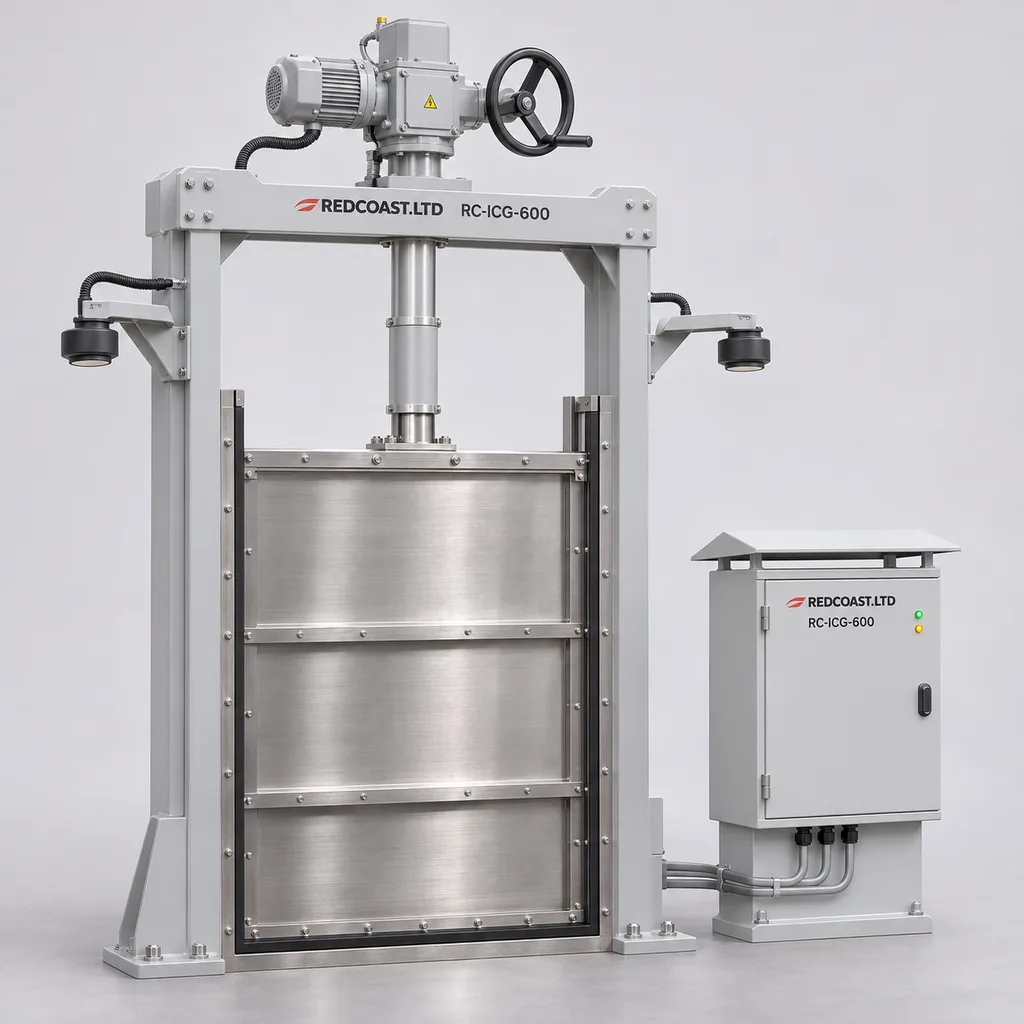
Overview
The RC-ICG-600 is an automated irrigation canal gate and water level control station for irrigation authorities, agricultural estates, water utilities, and infrastructure integrators operating sites with an existing mains supply. It combines a motorized slide gate, upstream and downstream level instruments, local control, a Web management platform, and a mobile App to reduce repeated manual adjustments and make delivery changes traceable. REDCOAST.LTD develops the station electronics in-house, including project-specific PCB layouts, isolated sensor acquisition, actuator interfaces, and embedded control firmware. The principal operating task is to maintain a selected canal pool level or gate position while respecting hydraulic limits, actuator duty, and local operating authority.
Key Features
- One complete regulating station: A reference 1,000 mm wide by 1,200 mm high slide gate, electric operator, two radar level sensors, outdoor cabinet, Web dashboard, and mobile maintenance workflow form a defined supply package.
- Local closed-loop control: Select upstream level, downstream level, or gate-position control, with a configurable 10–50 mm level deadband and movement limits suited to the canal response.
- Purpose-built electronics: Custom acquisition and control PCBs provide four isolated analog inputs, two isolated RS-485 ports, twelve digital inputs, and six relay outputs.
- Independent movement protection: End-of-travel switches, torque protection, motor thermal protection, direction interlocking, and a hardwired stop circuit act outside the cloud connection.
- Useful operating records: Trends combine both water levels, gate position, operating mode, motor starts, alarms, and operator commands so maintenance teams can investigate recurring problems.
- Optional measured-flow control: An external flow instrument can close the flow-control loop; gate position alone is not presented as an accurate delivery meter.
- Network-loss continuity: A validated local setpoint remains active during communication loss, with timestamped records uploaded after reconnection.
- Practical retrofit scope: Gate-only, controls-only, and complete replacement packages can accommodate serviceable civil structures after dimensional and mechanical inspection.
Technical Architecture
The reference mechanical assembly uses a vertically lifting, three-side-sealing stainless-steel gate with a flush-bottom seal, low-friction polymer guides, a protected screw mechanism, and an electric operator with manual handwheel. The reference leaf measures 1,000 mm across the channel and 1,200 mm vertically, with 1,200 mm of travel. At the reference travel speed of 100 mm/min, a complete stroke takes 12 minutes; the selected operator must permit that uninterrupted run at the required load. Its quotation design basis is a maximum 1.0 m differential head, with the water surface kept below the top of the closed leaf; this is an open-channel regulating gate, so overtopping must be considered in the civil design. The published figures define an engineered-to-order reference configuration, not completed type-test results; final dimensions, loads, leakage limits, and acceptance criteria are fixed in the approved project submittal.
Inside the cabinet, a REDCOAST.LTD acquisition PCB conditions isolated 4–20 mA signals and communicates with digital instruments. A separate actuator-interface PCB monitors travel limits, fault contacts, position feedback, and movement commands, while appropriately rated industrial contactors or the operator's own motor controller switch motor power. The embedded controller filters transient surface disturbance, checks signal freshness, and calculates a bounded position correction. An upstream-level loop and a downstream-level loop require different control action; the selected direction, deadband, minimum movement, and settling time are verified during wet commissioning rather than copied between sites.
The edge controller retains the active schedule, alarm rules, and movement permissions. The Web platform provides asset mapping, trends, schedules, user permissions, and command history, while the App supports inspection records and alarm acknowledgement. Remote commands expire if they arrive late and require an acknowledgement containing the resulting operating state. For multiple canal pools, supervisory scheduling accounts for travel time and available storage; simultaneous commands to several gates are not assumed to produce immediate downstream delivery.
Connectivity & Power
The standard station uses a dedicated AC 220–240 V, single-phase, 50/60 Hz supply. An AC 380–415 V, three-phase actuator package is an alternative build with its own correctly rated control-power supply. The reference motor has a 0.37 kW rated mechanical output; the electrical connected-load planning allowance is 0.9 kW for the reference assembly, including controls and a 60 W cabinet heater but excluding motor starting current. Supply cable, protective devices, earthing, and voltage-drop calculations follow the selected motor nameplate and installation conditions.
Ethernet suits staffed headworks and pump stations, while an industrial LTE router serves sites with cellular coverage. Fiber conversion is an option where distance or ground-potential differences make copper links unsuitable. Field devices connect through isolated RS-485 or analog loops; Modbus TCP/RTU supports existing SCADA, and MQTT over TLS carries platform telemetry. Remote access uses authenticated accounts and a controlled network path, without exposing an unauthenticated fieldbus service to the public internet.
This configuration uses mains power throughout. On a power outage, the specified self-locking or braked drive holds the gate mechanically, and manual operation remains available under the site's isolation procedure. The base package cannot move the gate or transmit live alarms after loss of its supply. Automatic movement after an outage requires a separately engineered external standby supply sized for the motor, starting demand, and required travel.
Protection & Reliability
The cabinet design target is IP66, with sealed cable entries, a rain and sun shield, an anti-condensation heater, and separated mains and instrumentation wiring. Exterior carbon-steel cabinets and mounting supports receive hot-dip galvanizing beneath a smooth powder-coated or fluorocarbon-painted finish; submerged gate parts use suitable stainless steel instead. Sensor heads are selected with IP66/IP68 protection, and the operator with at least IP67 protection, while the complete installed assembly requires its own ingress assessment. IP ratings do not establish corrosion resistance or authorize cabinet submersion.
The reference ambient design envelope is -20 to +55 °C with the specified thermal arrangement and liquid, unfrozen water. Direct solar loading, salt exposure, wind loads on brackets, and sediment conditions are reviewed separately; a cabinet heater does not de-ice a canal or a jammed gate. Torque trips, inconsistent position feedback, or an invalid control-level signal stop automatic movement and generate a latched fault while power remains available. Independent high-level contacts can inhibit a hazardous direction, with the action determined by the upstream and downstream hydraulic consequences.
Routine maintenance covers screw lubrication, seal inspection, sediment removal, sensor alignment, and terminal checks. Replaceable boards, documented terminal assignments, configuration backups, and stocked seals make servicing practical. Warranty duration, spare-parts availability, firmware support, and response commitments are specified in the supply agreement against the agreed environment and maintenance plan.
Application Scenarios
- Irrigation district branch canals: Install the station at a powered check structure or offtake where manual adjustment cannot follow changing deliveries. Local regulation maintains the selected pool condition and gives operators a record of each scheduled change.
- Pump-fed irrigation canals: Place the station downstream of an existing pump facility with mains and SCADA available. The controller can regulate the receiving pool and exchange permissive signals with the pump station, while pump protection remains within the pump-control system.
- Large agricultural estates: Use a station at each powered distribution junction supplying several surface-irrigated blocks. Timed position schedules and optional measured-flow feedback make rotations visible to the estate's water manager.
- Nursery and horticultural water distribution: Fit a smaller gate at the outlet of a balancing basin feeding open irrigation channels. Level trends help operators distinguish a supply shortfall from an outlet setting that is inappropriate for current demand.
- Canal modernization programmes: Retain structurally sound concrete works and replace worn gate mechanics, instrumentation, and local controls as needed. A phased rollout allows hydraulic settings and maintenance practices to be established before more stations are connected.
Demand for this category is reflected in published 2025 water-efficiency projects specifying automatic headgates, canal checks, and flow sensors for improved irrigation control. These procurement examples establish a use case, not performance evidence for the RC-ICG-600. WaterSMART FY2025 project descriptions.
Case-style Examples
The following examples are illustrative engineering scenarios, not reported REDCOAST.LTD installations or measured savings claims.
Powered branch-canal modernization. An irrigation operator has a manually adjusted gate near an existing electrical service and receives complaints about varying upstream levels during delivery changes. The proposed configuration uses the reference slide gate, two radar sensors, LTE telemetry, and upstream-level control with a commissioning starting deadband of 20 mm. The intended result is automatic correction within agreed limits and a shared event history that helps explain disturbances; the final control band is established through wet tests.
Pump-station receiving-pool regulation. A distribution facility needs to keep a receiving canal within an operating band as pumps start and stop. A three-phase operator package, wired Ethernet, downstream-level control, and hardwired pump-status inputs allow the gate schedule to follow the facility's operating sequence. Acceptance testing checks pump transitions, sensor loss, and communication failure so the resulting response is documented before unattended operation.
Measured irrigation delivery at a canal turnout. An estate wants scheduled volume reporting at a powered offtake. The station receives flow data from a separately specified meter and integrates only valid readings, flagging missing intervals rather than inventing consumption. The intended outcome is an auditable operational delivery record; any use for billing requires the meter, installation, and verification process demanded by the applicable authority.
Customization & Selection Guide
Start with the channel survey: clear width, invert elevation, available height, maximum upstream and downstream levels, sediment loading, and both seating and reverse-pressure conditions. The 1,000 × 1,200 mm reference gate suits quotation discussions; 600 × 800 mm and 1,200 × 1,500 mm alternatives require separate structural, thrust, stroke, and civil checks. Specify whether an existing gate is retained, because a new controller cannot correct bent stems, damaged guides, or leaking seals.
Choose position control for simple scheduled openings, upstream-level control to stabilize the supply pool, or downstream-level control to maintain the receiving pool. Flow control needs a suitable external meter or an independently validated hydraulic rating; the same gate opening can pass different flows as head changes. Procurement documents should distinguish sensor accuracy, achieved level-control performance, and totalized-flow uncertainty. Published component references support these selection boundaries: the ORBINOX CC catalogue, June 2024 distinguishes three-side sealing and allowable head, while the VEGA VEGAPULS C 21 specification documents an industrial 80 GHz radar with ±2 mm reference accuracy. These references do not certify the complete station.
For constrained budgets, begin with one gate, two level sensors, local controls, and Ethernet. Add LTE where a wired network is unavailable, independent level switches where the hydraulic risk assessment requires them, and a measured-flow interface where delivery reporting justifies it. Include operator duty, maximum starts, manual access, coatings, required languages, and the customer SCADA tag list in the enquiry.
Deployment & After-sales
Installation begins with approved civil and electrical drawings, a dewatering or bypass plan, and verification of the supporting concrete. The cabinet stands above the project design flood level, and radar sensors are positioned away from the gate jet, obstructions, and unstable surface zones. Both level channels use a surveyed common datum; independent staff gauges provide a practical commissioning cross-check.
Factory acceptance covers wiring, I/O scaling, simulated signal faults, travel permissions, command expiry, and power-cycle behavior. Site acceptance adds full gate travel, torque settings, leakage at the agreed head, manual operation, and wet-loop tuning across representative operating conditions. Hydraulic acceptance is distinct from checking that the dashboard receives data.
Delivery planning separates custom PCB development, prototype verification, mechanical fabrication, software integration, and the site's shutdown window. The quotation establishes these milestones after the survey and interface specification are agreed. Handover includes schematics, PCB assembly identifiers, terminal schedules, instrument records, firmware versions, operating instructions, and a spare-parts list, with remote support and installer training scoped to the project.
Standards & Compliance
The tender can nominate AWWA C561-21 for fabricated stainless-steel slide gates and AWWA C542-16(R21) for electric motor actuators, or the locally required equivalents. These are separate mechanical procurement references; the applicable edition and any deviations must be fixed at contract stage. AWWA standards catalogue.
Ingress verification follows IEC 60529 for each specified enclosure configuration. Where the cabinet falls within their scope, IEC 61439-1:2020 and IEC 61439-2:2020 provide the assembly verification framework. IEC 60529, IEC 61439-1, IEC 61439-2.
For industrial installations without a more specific applicable EMC standard, the assessment plan can use IEC 61000-6-2 immunity and IEC 61000-6-4 emissions requirements. The final installation environment determines the applicable tests. IEC 61000-6-2, IEC 61000-6-4.
CE marking, radio approvals, and RoHS documentation are addressed according to the supplied configuration and destination requirements. No certification, verified leakage class, or completed product test is implied by this reference specification; the delivered documentation must identify the exact assembly and its supporting evidence.
Why REDCOAST.LTD
REDCOAST.LTD delivers the complete station: mechanical and electrical coordination, purpose-built electronics, embedded control, Web management, and the mobile App. In-house board-level design allows sensor isolation, actuator feedback, terminal arrangements, protection circuits, and communications to be changed for the actual project, including development of a new PCB when required. This makes it possible to accommodate an existing canal structure and SCADA workflow without limiting the solution to the interfaces of a fixed commercial controller.
The project remains one coordinated hardware and software scope, with clear responsibilities for purchased instruments and actuators as well as the electronics developed by REDCOAST.LTD. Buyers receive a configuration tied to surveyed hydraulic conditions and explicit acceptance criteria, rather than a generic water-saving percentage.
Send REDCOAST.LTD your channel drawings, water-level limits, available mains supply, and SCADA requirements to request a customized RC-ICG-600 station proposal.
Specifications
Gate & Hydraulic Design Basis
- Reference Gate Width × Leaf Height
- 1000 × 1200 mm
- Alternative Width × Leaf Height
- 600 × 800; 1200 × 1500; separately engineered mm
- Reference Maximum Differential Head
- 1.0; water surface below closed leaf top; seating and unseating loads verified separately m
- Gate Configuration
- Vertical slide; three-side sealing; flush-bottom sill
- Reference Gate Travel
- 1200 mm
- Gate Leaf & Wetted Frame
- 316L stainless steel; 304L option after water chemistry review
- Seal & Guide Materials
- EPDM seals; UHMWPE guides
Electric Actuation
- Reference Motor Rated Output
- 0.37; mechanical output, not AC input consumption kW
- Reference Drive Thrust Selection
- 10; final operating and trip settings follow gate load calculation kN
- Reference Linear Travel Speed
- 100 mm/min
- Reference Full-Stroke Travel Time
- 12 at 1200 mm travel; subject to actuator duty allowance min
- Gate Position Indication
- 0–100; 0.1% display resolution, not positioning accuracy %
- Software Movement Limits
- 60 starts/hour maximum; 15 minutes cumulative run/hour maximum; OEM thermal limits take precedence
- Manual & Protective Functions
- Handwheel; mechanical holding brake or self-locking drive; two end limits; torque and thermal trips
Level Measurement & Control
- Level Sensor Quantity
- 2; upstream and downstream
- Measurement Principle
- Non-contact 80 GHz radar
- Configured Sensor-to-Water Distance
- 0.3–5.0; installation-specific m
- Specified Sensor Reference Accuracy
- ±2 under selected sensor manufacturer's reference conditions; excludes site and control error mm
- Acquisition Interval
- 1–5, matched to sensor update rate s
- Level Control Deadband Width
- 10–50 total width; initial commissioning setting 20 mm
- Control Modes
- Gate position; upstream level; downstream level; external measured-flow feedback option
- Single Movement Increment
- 5–50; tuned to canal response and actuator resolution mm
Custom Electronics & Field I/O
- PCB Functional Modules
- Isolated acquisition/main controller; actuator I/O interface; protected DC distribution
- Isolated Analog Inputs
- 4 × 4–20 mA; 16-bit conversion
- Isolated Serial Ports
- 2 × RS-485; 1200–115200 baud
- Digital Inputs
- 12 × 24 V DC; limits, faults, level contacts, and local selector
- Relay Outputs
- 6 dry contacts; 30 V DC, 2 A resistive maximum; interface loads only
- Optional Analog Output
- 1 × isolated 4–20 mA actuator setpoint
- Local Operator Interface
- 4.3-inch display behind locked door; Local/Off/Remote selector; Open/Stop/Close controls
Mains Power
- Standard Supply
- AC 220–240; single phase V
- Alternative Actuator Supply
- AC 380–415; three phase; matching control-power transformer or supply V
- Supply Frequency
- 50 / 60; motor and gearing selected for ordered frequency Hz
- Internal Control Supply
- 24 V DC; 100 W rated supply
- Reference Controls Consumption Budget
- 20–35; controller, two sensors, display, and LTE router; motor and heater excluded W
- Cabinet Heater
- 60; thermostat/hygrostat controlled W
- Reference Connected-Load Allowance
- 0.9; reference motor, controls, and heater; excludes motor starting current kW
- Supply-Loss Behavior
- Mechanical position hold; no powered movement or live telemetry until supply returns
Communications & Software
- Ethernet Interface
- 1 × 10/100BASE-T
- Remote Uplink Options
- Ethernet; industrial 4G LTE router; fiber media converter
- Integration Protocols
- Modbus RTU; Modbus TCP; MQTT over TLS 1.2 or later
- Telemetry Interval
- 10–300; event transmission on alarm while connected s
- Local Trend Retention
- 90 days at 60-second intervals for up to 32 numeric tags
- Management Interfaces
- Web dashboard; Android/iOS App; HTTPS REST API
- Access & Command Controls
- Role permissions; unique device credentials; command expiry; command acknowledgement and audit log
Enclosure & Environmental Design Targets
- Cabinet Ingress Target
- IP66; complete assembly verification required
- Selected Field Device Protection
- Operator IP67 minimum; radar sensor IP66/IP68 per ordered device conditions
- Ambient Design Range
- -20 to +55 with specified thermal arrangement; liquid, unfrozen water °C
- Ambient Humidity
- 5–95% RH; internal condensation controlled by heater and sealed entries
- Reference Cabinet Height × Width × Depth
- 700 × 500 × 300; excluding plinth and sun shield mm
- Cabinet & Dry Support Finish
- Hot-dip galvanized steel base with smooth matte powder coating; RAL 7035 or RAL 7016
- Coastal Finish Option
- Compatible primer system and smooth fluorocarbon topcoat; exposed stainless grade selected for chloride conditions
Capabilities — configurable per project
Specifications are tailored to each project — the options below show what we can support.
Mechanical Supply Scope
- Complete gate, operator, and control station
- Operator and control retrofit for an inspected existing gate
- Control cabinet and instruments for an existing electric operator
Hydraulic Control Package
- Scheduled gate position
- Upstream pool level regulation
- Downstream pool level regulation
- External metered-flow regulation
Mains & Network Configuration
- Single-phase 230 V with Ethernet
- Single-phase 230 V with LTE
- Three-phase 400 V operator with fiber network interface
Site Materials & Finish
- 316L wetted parts with RAL 7035 cabinet
- 304L wetted parts for assessed freshwater conditions
- 316L wetted parts with fluorocarbon-coated coastal cabinet
Software Delivery
- Hosted Web platform and mobile App
- Customer-hosted management platform
- Existing SCADA integration with documented register map
Related solution guidance

Environmental Monitoring
Deploy environmental monitoring stations with sensors, solar power, gateways, dashboards, alarms and data integration for city and industrial sites.
Power and Connectivity
How to choose power, battery, solar, NB-IoT, LTE, LoRaWAN, gateways and monitoring strategy for outdoor IoT infrastructure.
Campuses
Campus IoT for lighting, parking, safety, smart poles, environmental data and facility maintenance workflows.
Frequently Asked Questions
What does an automated irrigation canal gate control?
The RC-ICG-600 adjusts a motorized slide gate to maintain a selected upstream level, downstream level, or gate position. It uses local sensor feedback and movement limits, so routine regulation can continue without a live cloud connection. Flow-control operation requires a suitable external measurement input or a separately validated hydraulic rating.
Can the RC-ICG-600 retrofit an existing manual canal gate?
Yes, after the gate, stem, guides, supporting structure, and available operating space have been inspected. The retrofit can include an electric operator, radar sensors, a custom control cabinet, and platform integration. A worn gate or excessive leakage may require mechanical replacement before automation is useful.
Does the station need solar panels or an off-grid power system?
This model is configured for sites with an existing mains service, using single-phase AC 220–240 V or an alternative three-phase AC 380–415 V operator package. It does not include solar equipment. The 0.37 kW reference motor rating describes mechanical output; supply sizing uses electrical input, starting demand, cable length, and auxiliary loads.
What happens when internet connectivity or mains power fails?
During communication loss, a healthy local controller continues the approved operating mode and records data for later upload. During mains failure, the specified brake or self-locking drive holds the gate, but the base station cannot move or send live telemetry. Any required automatic outage movement needs an independently sized external standby supply and a defined hydraulic response.
How accurately can the station maintain canal water level?
The reference sensor specification is ±2 mm under the instrument manufacturer's stated reference conditions, while the configurable control deadband is 10–50 mm. Neither number guarantees that the canal surface will remain within that band during changing demand. Waves, sensor position, gate backlash, canal storage, and transport delay determine the achieved performance, which is measured during wet commissioning.
Can gate opening be used to calculate billable irrigation volume?
Gate opening alone does not determine flow because upstream level, downstream level, and hydraulic conditions also matter. Operational totals should use an appropriate flow instrument or a validated site-specific rating, with invalid data intervals flagged. Billing requires the metering and verification arrangements accepted by the responsible authority; the base gate station is not presented as a certified revenue meter.
Does REDCOAST.LTD design the electronics or only integrate purchased controllers?
REDCOAST.LTD develops the station's acquisition, control, actuator-interface, and protected power-distribution electronics, including custom PCB and board-level design. Project requirements can change the I/O mix, isolation, connectors, firmware behavior, and platform integration. Industrial sensors and mechanical operators are selected components within the complete hardware, Web, and App solution.
What information is needed for a firm quotation?
Provide channel drawings, gate dimensions, upstream and downstream operating levels, maximum differential head in each direction, and the available mains supply. Also identify sediment and water chemistry, ambient conditions, operating frequency, network availability, and required SCADA interfaces. These inputs determine gate construction, actuator sizing, electronics configuration, civil interfaces, and the delivery and acceptance schedule.