Overview
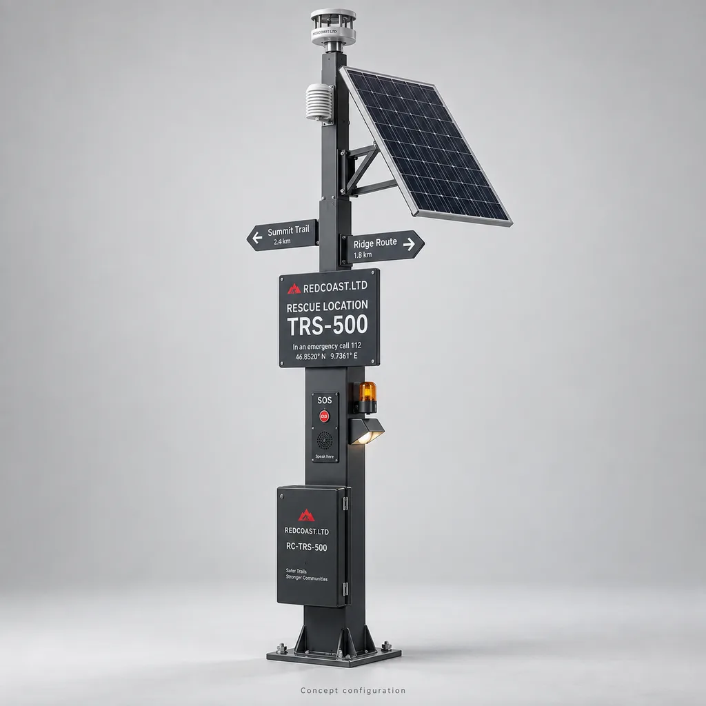
The RC-TRS-500 is a configurable mountain trail safety and rescue coordination pole from REDCOAST.LTD, combining a permanent rescue location code, hands-free emergency intercom, local weather sensing and illuminated route information. It is intended for park authorities, trail operators and outdoor event organizers managing remote paths where electricity, mobile reception and maintenance access vary between locations. Each pole becomes a mapped operational asset associated with a trail segment, nearby evacuation routes and responder access instructions, helping operators turn a request for assistance into an actionable incident record. The reference configuration uses solar power because its intended installation sites lack an electricity supply; the specifications below are proposed engineering values for project configuration, with final performance established through site assessment and acceptance testing.
Key Features
- Permanent rescue location identity: A large reflective alphanumeric code links the physical pole to verified coordinates, trail chainage and responder access notes. The code remains readable without electricity, a smartphone or a functioning network.
- One-button emergency conversation: A recessed SOS button initiates a hands-free SIP call to an agreed staffed control point, with separate indications for call initiation, connection and communication failure.
- Trail segment management: Operators associate poles with route sections, junctions and evacuation exits, then distribute approved warnings or closure messages to selected sections rather than the entire network.
- Local weather observations: An unheated ultrasonic wind sensor and shielded temperature/humidity probe provide measurements close to visitor exposure, with configurable thresholds, persistence timers and sensor fault checks.
- Low-power wayfinding: Reflective direction plates, a shielded marker light and an optional electronic paper information panel provide route information without a large continuously powered display.
- Defined communication fallback: Optional satellite short messaging transmits the pole identity and incident status when cellular service is unavailable, with explicit separation between message delivery and live voice connectivity.
- Visible equipment health: Battery state, charging yield, network registration, enclosure tamper and sensor status feed a maintenance dashboard and mobile work queue.
- Project-specific electronics: REDCOAST.LTD develops the controller, audio interface, sensor interface, lighting driver and power-management PCBs, allowing electrical interfaces and operating logic to be adapted to the project.
Technical Architecture
The pole integrates five functional assemblies: a visitor interface, a low-power controller, a weather sensor package, a communication subsystem and a protected DC power system. The visitor interface combines the SOS button, microphone, loudspeaker, status indicators and reflective location plate. A REDCOAST.LTD controller reads the button and tamper inputs, acquires sensor data over RS-485, manages the marker light and supervises separate power branches. Commercial radio modules and sensor heads connect to purpose-designed carrier and interface boards; custom PCB development concerns the product electronics, rather than manufacturing cellular chipsets or satellite networks.
When the SOS button is pressed, the controller records the pole ID and timestamp, starts the configured call sequence and sends an incident event containing stored coordinates, recent weather readings and equipment status. The Web platform displays the associated trail segment, nearest approved responder access point and operator-maintained evacuation notes. Live GNSS is optional because a fixed pole can use surveyed coordinates stored during commissioning. Operators acknowledge, assign and close incidents through role-based workflows; the system distinguishes an uploaded event, an operator acknowledgement and an answered voice call.
Weather rules run locally so that a permitted warning can activate during a cloud outage. Rules include measurement validity, threshold duration, hysteresis and an expiry time for remotely issued instructions. A failed sensor produces a fault state rather than a fabricated safe reading. Local storage preserves telemetry and event metadata for later upload, while audio recording is disabled by default and requires an explicitly configured retention policy. Remote software updates use signed packages and rollback handling, and the platform separates maintenance access from authority to publish route instructions.
Connectivity & Power
The reference configuration uses a region-appropriate 4G LTE modem with two SIM slots and one active connection. SIP audio reaches the customer's PBX or hosted dispatch service over the available IP connection. Changing SIMs requires network registration and can interrupt a call; it is not seamless dual-network voice redundancy. Coverage must be measured at the proposed mounting location, because a pole can communicate where a visitor's handset cannot only when its antenna placement or network selection provides a usable link.
For locations beyond cellular coverage, the optional satellite module provides short incident messages and return acknowledgements. This follows the service category described by Iridium Short Burst Data: packet messaging between field equipment and a central system. The option does not carry the SIP conversation. Sites requiring voice with no terrestrial service need a separately engineered satellite voice or IP backhaul package, including antenna clearance, service subscriptions and a revised energy budget. No radio option removes the need for an attended response arrangement.
The reference power package comprises a 200 Wp photovoltaic module, a 25.6 V 80 Ah LiFePO4 battery and a 15 A MPPT controller. Its daily design allowance is 160 Wh: 120 Wh for a 5 W continuously available electronics load, 24 Wh for a 2 W marker operating for 12 hours, 10 Wh for 30 minutes of additional 20 W call and signalling activity, and 6 Wh of operational margin. Optional heaters, cameras, satellite equipment and electronic paper updates require separate allowances.
Nominal storage is 2,048 Wh. Applying an 80% usable discharge window and 90% downstream efficiency gives approximately 1,475 Wh, or 9.2 calculated days at the reference load; the planning target is eight sunless days with a new, fully charged battery at approximately 20°C. A 200 Wp module receiving two equivalent peak-sun-hours with a 0.65 overall harvest factor supplies approximately 260 Wh per day, leaving about 100 Wh for recovery after serving the reference load. This is a sizing example, not a winter guarantee: canopy shading, snow, terrain horizon, battery aging and consecutive cloudy periods determine the final array and storage selection.
Protection & Reliability
The electronics enclosure is designed toward IP66 ingress protection, with an IK10 target for the user-accessible call enclosure. Exposed sensor heads, display windows and photovoltaic modules require their own environmental and impact specifications; the enclosure target is not a claim that every component withstands the same impact. The steel mast receives hot-dip galvanizing followed by a smooth matte powder-coated or fluorocarbon-painted finish. Sealed connectors, protected cable entries, replaceable acoustic membranes and corrosion-compatible fasteners support outdoor servicing.
The base system ambient design range is -20°C to +50°C, subject to battery cell temperature remaining within the selected pack's limits. Charging is inhibited below +5°C or above +45°C for the reference battery specification. Low-temperature protection is a practical requirement reflected in Victron's LiFePO4 operating guidance; exact limits must follow the battery actually supplied. An optional insulated, heated battery enclosure needs additional winter energy provision. The unheated wind sensor can become unreliable in icing conditions and must not be represented as an all-weather ice-free instrument.
Mast dimensions, foundations and panel brackets are checked against the site's wind exposure, ice accumulation and soil conditions. Surge protection and bonding are engineered with the installation earthing arrangement; the pole is not a lightning shelter. Reliability planning includes replaceable battery and radio assemblies, periodic voice-path tests and inspection after severe weather. Warranty duration, battery capacity criteria and service response commitments belong in the supply agreement rather than an unsupported universal lifetime claim.
Application Scenarios
Remote hiking junctions. Install poles where visitors choose between routes or where an evacuation path branches from the main trail. A readable location code and direction plates help callers describe their position, while the control room sees the correct access instructions.
Exposed ridge approaches. Place a sensor-equipped pole before visitors commit to an exposed section, with the sensor positioned to reduce mast and panel interference. Locally measured wind and temperature can trigger operator-approved advisory messages, while sensor height and terrain effects remain visible in the data record.
Mountain running course checkpoints. Associate each checkpoint pole with the event's route section, marshal contact and medical access plan. Scheduled marker illumination and an event-specific response roster support night operations, while the equipment remains a supplement to marshals, rescue resources and event procedures.
Mountain bike trail networks. Install poles at major junctions and responder access gates where an injured rider or companion can reach them. Unique codes reduce ambiguity between nearby loops, and voice communication lets the receiving operator clarify the incident and access conditions.
Remote recreational reservoir trails. Use poles on established walking routes where mains cabling would require extensive excavation. Weather observations and route status messages support visitor management, while the location register identifies land-based rescue approaches and does not imply water-rescue detection capability.
Case-style Examples
The following are illustrative deployment designs, not claims of completed installations or measured rescue outcomes.
Branching upland trail network. An operator managing an 18 km network identifies six junctions and two responder access points as priority locations through a route risk assessment. Eight poles receive reflective IDs and cellular intercoms; two locations with unreliable terrestrial service add satellite incident messaging after sky-view testing. The intended operational result is a consistent incident map linking each pole to an access gate and trail segment, with final spacing determined by terrain and visitor movement rather than a uniform distance rule.
Seasonal overnight endurance event. An organizer selects five established checkpoints for safety poles, with temporary mounting arrangements engineered for the actual panel area and wind exposure. The system uses precharged battery packs, scheduled marker lighting and a staffed event control desk; battery reserve is calculated for the event duration without assuming useful solar generation. A pre-event drill verifies the complete button-to-operator workflow and confirms that satellite message acknowledgements are displayed differently from answered calls.
Shaded woodland approach with an open clearing. A proposed safety location has suitable visitor access but insufficient sunlight beneath the canopy. The design moves the photovoltaic module to a nearby clearing using a protected cable route, with conductor sizing checked for voltage drop, or relocates the complete pole if that produces a simpler maintainable installation. The configuration is accepted only after the worst-month energy calculation and radio survey support it.
Customization & Selection Guide
Start with the route map, staffing model and emergency access plan. Permanent rescue codes are already used at trail junctions to help callers identify their location, as described in official park visitor guidance. Assign codes through the operator's agreed location register and confirm how dispatch personnel will retrieve them; printing a code does not automatically register it with public emergency services.
Select communications next. Use cellular SIP where a surveyed data connection is dependable, satellite short messaging where event delivery is needed outside coverage, and separately engineered voice backhaul where continuous conversation is a requirement. Solar emergency telephones with cellular connectivity and protected enclosures are an established product category, illustrated by this manufacturer's solar hotline specification. The RC-TRS-500 adds route segment records, local weather rules and rescue workflow integration to that underlying function.
Choose sensing according to the decision it supports. An ultrasonic wind range of 0–60 m/s and digital serial integration are commercially realistic, as shown in the Gill GMX200 manufacturer datasheet. Final sensor selection must also consider icing, power demand and measurement exposure. Pole-height observations describe that installation and are not interchangeable with standardized meteorological measurements; temperature and humidity alone also do not provide a measured WBGT heat-stress index.
For limited budgets, retain the permanent code, reliable communication, battery supervision and reflective wayfinding before adding a display or camera. Expand solar and battery capacity when adding electrical loads. At locations with a dependable existing electricity supply, specify a separate mains-powered configuration without a photovoltaic module rather than installing unnecessary solar equipment.
Deployment & After-sales
Deployment begins with a site schedule containing coordinates, photographs, shading assessment, radio measurements and proposed rescue access notes. REDCOAST.LTD then develops the equipment configuration, energy calculation, foundation interface and platform asset structure. Custom electronics proceed through schematic design, PCB layout, prototype assembly and functional verification before the production configuration is frozen; delivery timing is agreed after the hardware scope, component availability and required tests are established.
Commissioning includes a real call to the designated response desk, location-code verification, simulated communication failure, battery alarm checks and a weather-rule test using controlled inputs. Installers record sensor orientation and measurement height, confirm signage and button accessibility, and document panel tilt and cable routes. Handover includes an asset register, configuration backup, maintenance instructions and operator training. Remote diagnostics and replaceable modules support maintenance, but visits are still required for panel cleaning, battery condition assessment, vegetation clearance and physical damage inspection.
Standards & Compliance
The project verification plan uses IEC 60529 for enclosure ingress protection and IEC 62262 for the specified impact protection target. ICT and audio equipment safety assessment references the applicable adoption of IEC 62368-1, with the edition and test scope selected for the destination market. EMC, radio authorization, restricted-substance requirements and battery transport documentation are reviewed against the final bill of materials and jurisdiction. CE marking, where applicable, concerns conformity of the delivered configuration and is not implied by a concept specification or an approved radio module alone.
The installation design also addresses structural loading, earthing, photovoltaic equipment selection and accessible operation where required. Environmental qualification can include thermal cycling, humidity and corrosion tests with agreed acceptance criteria. This product page does not claim existing third-party certification for the new model, automatic event-permit compliance, or a guaranteed emergency response time.
Why REDCOAST.LTD
REDCOAST.LTD delivers the field hardware, Web management platform and mobile application as one configurable trail safety solution. Its in-house hardware capability includes new PCB and board-level designs for sensor interfaces, intercom control, supervised lighting and battery power management, so project requirements can change the actual electronics and control behavior. That capability allows the physical pole, communication workflow, energy budget and maintenance tools to be developed together, while established specialist modules are selected where appropriate.
Share your trail map, coverage survey, winter climate and response workflow with REDCOAST.LTD to request a tailored RC-TRS-500 configuration and deployment proposal.
Specifications
Product Configuration & Mechanical
- Specification Status
- Proposed reference configuration; final values subject to project verification
- Mast Height Above Finished Ground
- 3.5 reference; 3.0–4.0 project options m
- Main Mast Section
- 150 × 150 × 4 reference steel hollow section; structural verification required mm
- Electronics and Battery Cabinet
- 650 × 400 × 300 reference, H × W × D mm
- Steel Surface Treatment
- Hot-dip galvanized substrate with smooth matte powder coat or fluorocarbon topcoat
- Reference Finish
- RAL 7016 anthracite with high-contrast reflective identification panels
- SOS Button Installation Height
- 1,000–1,200; final height and approach geometry per accessibility design mm
Rescue Interface & Wayfinding
- Emergency Call Interface
- 1 recessed push button; hands-free full-duplex SIP audio
- Loudspeaker Amplifier Output
- 5 rated W
- Call Destination Sequence
- Up to 3 configured SIP destinations
- Printed Rescue Identifier
- 6–12 alphanumeric characters; 50–80 mm character height
- Reflective Direction Plates
- 2–4 plates; nominal 450 × 120 mm each
- Shielded Marker Light
- 2 reference; 2,200–3,000 K warm white; scheduled or event-controlled W
- Incident Beacon
- 5 peak electrical input; amber reference; locally approved flash pattern W
- Optional Information Display
- 7.5-inch monochrome electronic paper; timestamped messages; 0 to +50°C update range
Local Weather & Location
- Wind Sensor
- 2-axis ultrasonic; unheated reference configuration
- Wind Speed Measurement Range
- 0–60 m/s
- Wind Speed Sensor Accuracy Target
- 0.3 m/s RMSE at 0–10 m/s; 3% RMSE at 10–40 m/s; 5% RMSE at 40–60 m/s
- Wind Direction
- 0–359°; ±3° target at 0.5–40 m/s under valid exposure
- Air Temperature
- -30 to +60 measurement range; ±0.3 accuracy target at -10 to +50 °C
- Relative Humidity
- 0–100 measurement range; ±3 accuracy target at 20–80, non-condensing %RH
- Sampling and Upload Intervals
- Wind: 1 s; temperature/humidity: 10 s; routine upload: 60–300 s
- Location Record
- Commissioned WGS84 coordinates plus trail ID and chainage; optional GNSS: 2.5–5 m typical open-sky accuracy
Communications & Integration
- Primary Backhaul
- 4G LTE Cat 1 or Cat 4 module; destination-specific bands
- SIM Arrangement
- 2 SIM slots; 1 active modem connection; re-registration required during failover
- Voice Protocols
- SIP 2.0; G.711 or G.722; TLS/SRTP with compatible PBX
- Optional Satellite Interface
- Iridium SBD-class two-way short messaging; incident metadata only; no voice
- Service Ethernet
- 1 × 10/100BASE-T port inside locked enclosure
- Field Interfaces
- 2 × isolated RS-485; 2 × dry-contact inputs; 2 × protected switched DC outputs
- Platform Interfaces
- MQTT over TLS; HTTPS REST API; CSV and GeoJSON asset export
Off-grid Power & Energy
- Photovoltaic Array
- 200 reference; 200–400 project options; Vmp 36–42 V for reference configuration Wp
- LiFePO4 Battery
- 25.6 V, 80 Ah reference, 2,048 Wh nominal; 80–160 Ah project options
- MPPT Controller
- 15 A battery-side output; 100 V maximum PV open-circuit input
- Reference Electronics Standby Load
- 5 design allowance, including registered cellular modem and unheated sensors W
- Reference System Peak Load
- 50 design allowance; excludes optional heaters and additional backhaul W
- Reference Daily Energy
- 160; includes 12 h marker lighting and 30 min additional call/signalling activity Wh/day
- Sunless Autonomy Planning Target
- 8 at 160 Wh/day, new fully charged battery at approximately 20°C; no optional loads days
- Reference Battery Charge Window
- +5 to +45 cell temperature; BMS charge inhibit outside window °C
Environmental & Protection Targets
- Electronics Enclosure Ingress Target
- IP66; verification on complete assembled enclosure
- Call Enclosure Impact Target
- IK10; excludes PV module, exposed sensors and optional display window
- Base System Ambient Design Range
- -20 to +50; battery cell limits govern operation °C
- Internal Operating Humidity Target
- 5–95, non-condensing %RH
- Base Installation Altitude
- 0–2,000; higher sites require component and thermal review m
- Preliminary Structural Wind Basis
- 40 m/s three-second gust at 10 m reference height; terrain, topography, ice and local code review required
- Electrical Protection
- Battery branch fuse; reverse-polarity protection; PV and external signal surge protection; mast bonding point
Platform, Diagnostics & Maintenance
- Management Interfaces
- Web GIS dashboard plus Android/iOS maintenance application
- Local Telemetry Storage
- 30 days minimum design target at 1-minute aggregated records; excludes audio/video
- Health Heartbeat
- 60–900 configurable; 300 reference s
- Local Weather Rule Persistence
- 10–600 configurable; separate activation and clearance thresholds s
- Supervised Conditions
- Battery state and temperature; PV charging; network registration; sensor fault; enclosure opening
- Operator Roles
- 4 reference roles: observer, dispatcher, maintainer and administrator
- Maintenance Planning Interval
- 6–12 months plus post-storm inspection; shorten for shading, snow or contamination
Capabilities — configurable per project
Specifications are tailored to each project — the options below show what we can support.
Communications Package
- Dual-SIM cellular SIP with surveyed network coverage
- Cellular SIP plus satellite incident messaging
- Dedicated satellite voice or IP backhaul with revised power package
Off-grid Energy Package
- 200 Wp PV with 25.6 V 80 Ah LiFePO4 battery
- 400 Wp PV with 25.6 V 160 Ah LiFePO4 battery
- Remotely mounted PV array with engineered cable route
- Insulated battery enclosure with 20–40 W thermostatic heater and recalculated winter budget
Visitor Information
- Reflective rescue code and fixed directional plates
- Reflective plates plus 7.5-inch electronic paper status panel
- Tactile labels and project-selected language prompts
- Hearing-loop interface with power and accessibility assessment
Installation Environment
- Permanent foundation-mounted trail pole
- Engineered removable event mounting system
- Coastal corrosion package with fluorocarbon topcoat
- High-altitude package for 2,000–4,000 m following component and structural verification
Operations Platform
- Hosted Web platform and maintenance app
- Customer-hosted deployment
- Existing GIS and SIP/PBX integration
- Event-specific checkpoint roster and incident export
Related solution guidance
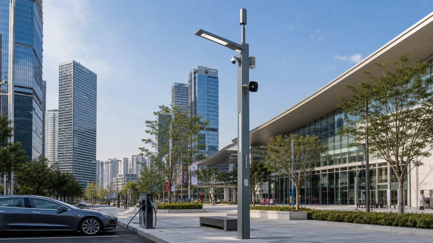
Campuses
Campus IoT for lighting, parking, safety, smart poles, environmental data and facility maintenance workflows.
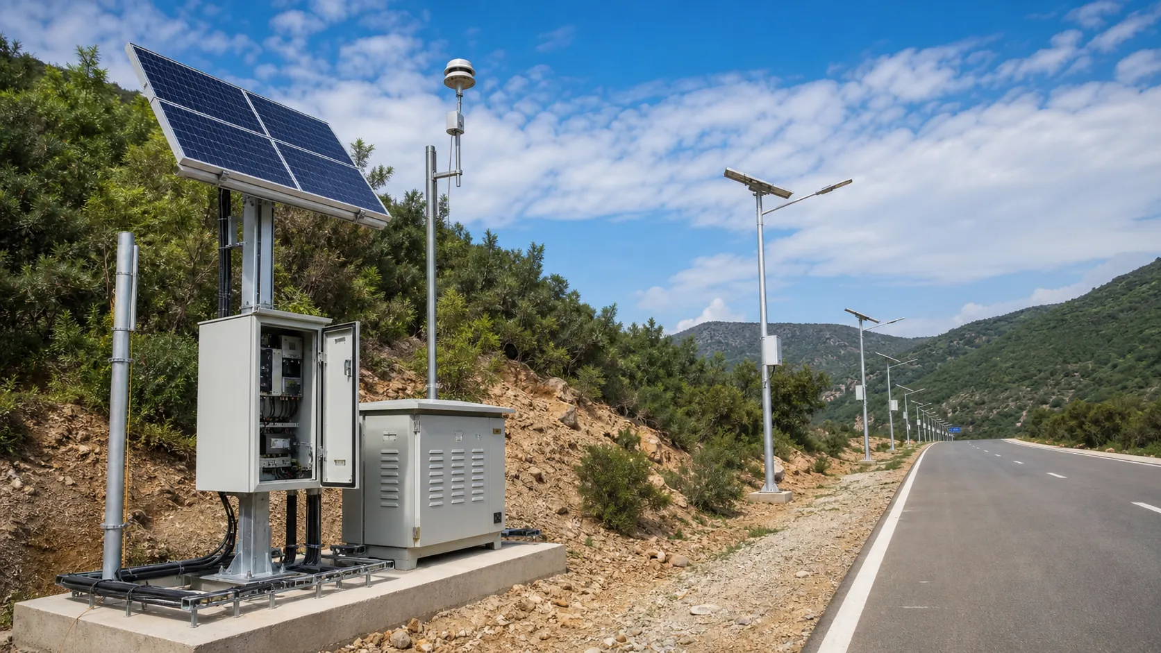
Ports and Logistics
Outdoor IoT infrastructure for ports, yards and logistics areas: lighting, guidance, safety, solar power, monitoring and maintenance visibility.
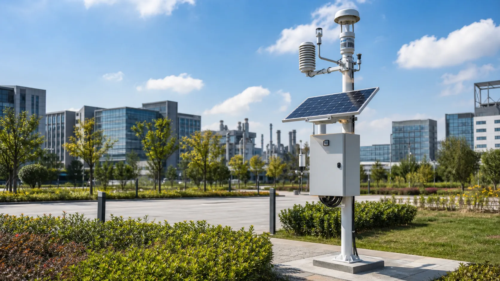
Environmental Monitoring
Deploy environmental monitoring stations with sensors, solar power, gateways, dashboards, alarms and data integration for city and industrial sites.
Frequently Asked Questions
How is a mountain trail safety pole different from a standard emergency call station?
The RC-TRS-500 combines emergency calling with a permanent rescue code, trail segment records, local weather rules and illuminated route information. Its platform associates incidents with responder access notes and evacuation routes maintained by the operator. This makes it a route management and rescue coordination asset as well as a call point.
Can the pole call for help where there is no mobile coverage?
The reference SIP voice service requires a working cellular IP connection. Optional satellite short messaging can transmit the pole identity and incident metadata outside cellular coverage, but it does not provide a voice conversation. Sites requiring satellite voice need a separate backhaul design, suitable antenna visibility, an active service plan and a revised energy calculation.
How long can the trail safety pole operate without sunshine?
The reference 25.6 V 80 Ah battery stores 2,048 Wh nominally. An 80% usable discharge window and 90% downstream efficiency provide approximately 1,475 Wh, equivalent to 9.2 calculated days at 160 Wh per day; the planning target is eight days with a new fully charged battery near 20°C. Cold weather, aging, extended calls and optional equipment reduce autonomy, so winter sizing requires site-specific calculations.
Does the rescue location code work without a phone or electrical power?
The reflective printed code and fixed direction plates remain visible without power. A visitor or responder can read the code, but transmitting a request still requires a functioning communication method or another person reaching assistance. The operator must register each code and its coordinates in the agreed dispatch workflow; printing a code alone does not connect it to public emergency services.
Can the pole automatically determine whether a trail is safe?
It can apply approved rules to valid local wind, temperature and humidity measurements and publish a warning when configured thresholds persist. Those observations do not assess every hazard, predict lightning or establish that an entire route is safe. Trail closure decisions and operating procedures remain with the responsible authority, and sensor faults or expired messages must be shown explicitly.
Will the solar system work under trees, in snow or at high altitude?
Dense shade and snow-covered modules can prevent adequate charging, so the array may need a nearby open location or the whole pole may need relocation. The reference battery blocks charging outside its specified cell-temperature window; a heated enclosure adds energy demand. Installations above 2,000 m require an additional component, thermal and structural review rather than assuming the base configuration remains suitable.
Does installing these poles satisfy outdoor event licensing or rescue requirements?
The equipment can support checkpoint communication, location identification and operational records, but installation alone does not establish compliance with event permits or rescue obligations. Requirements depend on the jurisdiction, route and event conditions. The organizer must establish staffing, escalation procedures, rescue resources and an acceptance drill with the intended response team.
Can REDCOAST.LTD develop custom hardware and integrate our existing platform?
Yes. REDCOAST.LTD can develop new PCBs and board-level hardware for intercom control, sensor interfaces, lighting and power management, alongside the Web platform and mobile application. Integration can use SIP, MQTT, HTTPS APIs and GIS asset exports, with interface details and acceptance tests agreed before development. Hardware changes require their own power-budget and verification review.