Overview
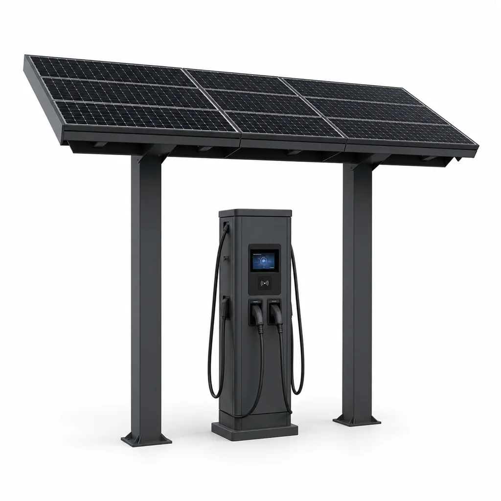
The RC-EVC-7040S is Redcoast's off-grid solar smart EV charging station, engineered for locations where utility grid access is unavailable, unreliable, or economically impractical—remote parking areas, national park trailheads, highway rest corridors, campus lots, coastal resorts, tourist destinations, and urban open-space deployments in grid-constrained emerging markets. Built around Redcoast's custom-designed multi-string MPPT charge management PCB and a high-capacity LiFePO4 energy storage bank, the station delivers 7.4–14.8 kW AC Level 2 charging (or 20–40 kW DC fast-charge in the RC-EVC-4040D variant) while remaining completely independent of the utility grid. Because every critical board—MPPT controller, battery management system (BMS), EV charge protocol controller, and IoT gateway—is designed at the PCB level in-house by Redcoast, every parameter can be tuned to the deployment environment: solar string topology, battery chemistry and capacity, connector type, charging protocol extensions, and IoT integration—none constrained by off-the-shelf module limitations.
Key Features
- Fully Off-Grid Solar + Battery Operation: 2,000–4,800 W monocrystalline solar canopy combined with a 20–100 kWh prismatic LiFePO4 battery bank delivers continuous charging sessions regardless of grid availability, eliminating trenching, permitting, and distribution infrastructure cost.
- Redcoast Custom MPPT Power Management PCB: Proprietary 2–4 string multi-MPPT charge controller (Voc up to 450 V per string, synchronous buck topology, >98% peak efficiency) maximizes harvest under partial shading, high-temperature derating, and diffuse-light conditions.
- OCPP 2.0.1 Smart Charging Protocol: Full OCCP Alliance OCPP 2.0.1 compliance enables operator-grade backend integration, dynamic load management, per-session billing, remote diagnostics, and firmware OTA over any certified Central Management System.
- Flexible Connector Configuration: Type 2 (Mennekes), CCS2, CCS1, CHAdeMO, or GB/T connectors are configured per project at the PCB and firmware level—no costly adapters, one hardware design for global markets.
- 1–4 AC Level 2 Outlets or 1× DC Fast-Charge Module: Scales from a single 7.4 kW outlet for low-traffic remote sites to a dual 2×7.4 kW canopy pedestal or a 20–40 kW DC fast-charge unit for higher-throughput fleet or transit needs.
- IoT Telemetry & Remote CMS: Cellular 4G LTE / 5G uplink publishes real-time battery SOC, solar yield, per-port energy delivery, fault codes, and session history to Redcoast Cloud or any third-party OCPP/SCADA backend.
- Smart Energy Dispatch Firmware: Charging windows are automatically aligned with peak solar generation; battery discharge is protected by configurable low-SOC cutoff thresholds; grid-supplement relay is triggered during extended overcast periods in hybrid configurations.
- IP65 Electronics + IK10 Charge Point: Full dust exclusion and water-jet protection for all power electronics; impact-rated vandal-resistant housing on the charge point pedestal for high-exposure public installations.
- Multiple Access & Payment Modes: RFID card (ISO 14443 A/B), QR code mobile payment, or open free-access mode—configured in firmware without hardware change, supporting both revenue-generating public stations and operator-controlled fleet lots.
- Adaptive Climate Tolerance: Standard operating range −30 °C to +55 °C; optional active battery thermal management for tropical or desert sites; salt-spray-tested structural frame for coastal deployments.
Technical Architecture
The RC-EVC-7040S is organized around three hardware subsystems, each designed and manufactured in-house by Redcoast.
Solar & Storage Subsystem: The integrated solar canopy (standard 2,000 W with five 400 W monocrystalline modules; expandable to 4,800 W with twelve modules on extended canopy frame) feeds two to four independent MPPT strings on Redcoast's proprietary charge management PCB. Each string uses a synchronous buck converter with galvanic isolation from the battery bus, continuously tracking maximum power via an enhanced Perturb & Observe algorithm with real-time temperature compensation. Harvested energy is stored in a 48 V or 96 V prismatic LiFePO4 cell stack (20–100 kWh nominal). Redcoast's custom BMS PCB monitors every cell's voltage and temperature at 1 Hz intervals, enforcing passive cell balancing, over-current cutoff, over-temperature protection, and accurate SOC/SOH reporting to the main gateway controller.
EV Charging Control Subsystem: Redcoast's EV charge controller PCB implements the full IEC 61851-1 Control Pilot PWM signaling stack and OCPP 2.0.1 JSON-over-WebSocket protocol in dedicated firmware. For AC Level 2 service the board drives a solid-state relay and a Class 1 energy meter (±1% accuracy), logging kWh, peak power, and session timestamps to local flash. For the RC-EVC-4040D DC fast-charge variant, an additional galvanically isolated DC-DC stage (wide-input 96–800 V output range) delivers target battery voltage directly to the vehicle. All firmware is field-updatable over cellular OTA, allowing protocol extensions, tariff logic changes, and feature additions without on-site engineer visits.
IoT Gateway & Monitoring Subsystem: A dedicated edge gateway module handles dual-SIM 4G/5G uplink, publishes MQTT telemetry to Redcoast Cloud or customer SCADA, and maintains a local SQLite session log to survive connectivity gaps of up to 30 days. The gateway PCB drives a 4-inch color TFT status display showing battery percentage, active charging power, and QR code for mobile payment enrollment. Optional RS-485 Modbus output connects to building energy management systems (BEMS) for campus-level power accounting.
Connectivity & Power
Communication: Standard 4G LTE CAT-4 with optional 5G NR sub-6 GHz uplink; dual SIM slots for carrier redundancy in areas with single-operator coverage. Local Ethernet RJ-45 (with optional PoE-out for a companion security camera) for wired backhaul on campus deployments. BLE 5.0 for local mobile app pairing and commissioning. All cloud communication uses OCPP 2.0.1 JSON over TLS 1.3-encrypted WebSocket, compatible with any OCCP-Alliance-certified CMS.
Power Supply Modes:
- Fully Off-Grid Solar + Battery (standard): Solar array charges LiFePO4 bank; charging sessions draw from battery, replenished during daylight. Sized for 2+ cloudy-day autonomy at rated outlet count.
- Solar + Battery + Grid Hybrid: AC mains input (single-phase 220–240 V or three-phase 380–415 V) supplements solar during extended overcast periods and recharges battery overnight; solar reduces grid energy cost by 60–85% under typical insolation.
- Wind-Solar Hybrid: 400 W–3 kW small wind turbine input accepted on a dedicated MPPT input string; recommended for coastal and high-altitude sites with consistent wind resources.
- Grid Backup Only: Solar offset reduces operational cost; grid ensures 100% uptime regardless of weather.
Protection & Reliability
All power electronics are housed in an IP65-rated enclosure with die-cast aluminum heatsink for passive thermal management. The charge outlet pedestal housing meets IK10 (20-joule impact resistance) per IEC 62262. The structural canopy frame is hot-dip galvanized for baseline corrosion protection, then finished with smooth matte powder coating (standard RAL 7016 anthracite; RAL 9003 signal white and RAL 5015 sky blue available) or fluorocarbon paint for marine-grade deployments. Frame design is validated to withstand 55 m/s sustained wind loads.
LiFePO4 battery cells are rated for more than 6,000 full charge-discharge cycles to 80% remaining capacity at 25 °C, with an optional active heating/cooling module extending cycle life in climates above 40 °C or below −10 °C ambient. Surge protection devices (SPD) rated at 20 kA protect both DC solar input and AC grid input buses. Lightning protection topology follows IEC 62305 Level III. Mean time between failures (MTBF) for the power electronics subsystem is targeted at greater than 80,000 hours.
Application Scenarios
-
Remote National Park & Nature Reserve Parking: Trailheads and visitor center lots deep inside protected areas cannot receive grid extensions without environmental impact. The RC-EVC-7040S installs on pre-cast pads with zero trenching, delivering reliable charging to ranger vehicles and visitor EVs while meeting the carbon-neutral infrastructure mandates common to national parks programs.
-
Highway Charging Corridor Buildout: Government transport agencies rolling out inter-city EV charging corridors deploy multiple RC-EVC-7040S canopy stations at 50–80 km intervals along new or upgraded highways, providing travelers with Level 2 top-up charging. Centralized OCPP operator dashboards monitor all stations from a single control room and collect per-session revenue data for public-private partnership accounting.
-
University & Corporate Campus Parking: Sustainability-mandated campuses need EV charging across large, distributed parking fields where adding sub-panel capacity to every lot is cost-prohibitive. Multiple dual-outlet RC-EVC-7040S poles share a unified CMS dashboard; automatic load balancing prevents transformer overload during evening peak, and session energy data feeds directly into ESG carbon reporting.
-
Coastal Resort & Island Marina: Resorts and marinas with limited private micro-grid capacity add solar EV charging without overloading diesel backup systems. Wind-solar hybrid mode uses offshore breeze to supplement storage during evening peak charge demand at marina slip parking and poolside drop-off zones.
-
Smart City Open Parking Integration: Municipal smart-city deployments integrate RC-EVC-7040S canopies with existing city-operated CMS infrastructure; charging data is published to the city open data portal, and the pole foundation can be shared with CCTV, environmental sensors, and public Wi-Fi nodes via Redcoast's Smart Pole ecosystem.
-
Last-Mile Logistics & Fleet Depot: Fleet operators in areas with unreliable utility supply install banks of RC-EVC-7040S canopies timed via smart dispatch to release stored solar energy during the 05:00–08:00 vehicle departure window, ensuring all vehicles depart fully charged while cutting daytime peak-demand utility charges.
Case-style Examples
Off-Grid Trailhead Charging Deployment: A regional parks authority needed to serve 40–60 EV visits per day at a trailhead parking area where grid extension through protected forest was prohibited by environmental regulations. Three RC-EVC-7040S units with 3,600 W solar canopies and 40 kWh batteries each were installed on pre-cast concrete pads within a single week, requiring no road opening or utility permits. IoT telemetry reported a 94% session completion rate (vehicles reaching target SOC before departure) over the first six operating months with zero grid consumption. The authority projects a 4-year hardware payback through visitor charging fees collected via QR mobile payment.
Coastal Resort Wind-Solar Hybrid Charging: A 300-room island resort sought to offer EV charging to guests without straining its 200 kW diesel-backed micro-grid. Six RC-EVC-7040S units were configured in wind-solar hybrid mode, each paired with a 1.5 kW coastal wind turbine. The combined fleet supplies up to 88 kWh of renewable charging daily, cutting diesel generator run-hours and allowing the resort to market zero-emission EV charging as part of its eco-certification. Charging sessions are billed directly to guest rooms through Redcoast CMS integration with the property management system (PMS).
Urban Smart-City Parking Retrofit: A municipality retrofitting 120 surface parking spaces with EV charging selected the RC-EVC-7040S for its tool-free solar canopy assembly and no-trench installation. The full 120-space deployment was completed in 8 weeks. OCPP 2.0.1 connectivity linked all units to the city's existing Charge Point Management System; automatic load-balancing across all 120 outlets prevented distribution transformer overload during evening peaks, and the city's carbon dashboard received live renewable-energy offset data.
Customization & Selection Guide
Low-Traffic Remote Sites (1–10 sessions/day): Single-outlet RC-EVC-7040S with 2,400 W solar canopy and 20 kWh LiFePO4 battery. Provides 2+ cloudy-day autonomy for a single outlet. Best for national park entry stations, remote ranger posts, eco-lodges, and rural community access points.
Medium-Traffic Parking (10–30 sessions/day): Dual-outlet RC-EVC-7040S with 3,600–4,800 W solar and 40–60 kWh battery. Add optional single-phase grid backup for sites with intermittent utility access. Suitable for highway rest stops, campus perimeter lots, resort parking, and municipal smart-city pilot zones.
High-Throughput Depot or Fleet (>30 sessions/day or overnight fleet): RC-EVC-4040D DC fast-charge variant (20–40 kW output) with 80–100 kWh battery bank and 4,800 W solar array. Wind-solar hybrid option recommended at wind-resource sites. Redcoast engineering team provides project-specific load-flow and battery-sizing analysis on request.
Harsh Climate Options: Active battery thermal management module (heating + cooling) for sites above 40 °C or below −10 °C ambient; enhanced salt-spray corrosion protection (1,000 h per IEC 60068-2-52) for coastal or marine environments; sand-and-dust sealed (IP66) enclosure option for arid desert deployments.
Monetization & Access Control: Open free-access (no payment hardware), RFID card-only for controlled fleet lots, or full QR-mobile-payment with revenue reporting for public-facing stations—all specified at order and configured in firmware without any hardware change.
Deployment & After-sales
The RC-EVC-7040S ships as a pre-validated kit: canopy frame (flat-pack, air-freight compatible), electronics pedestal, solar panel modules, battery cabinet with pre-wired cell harness, and complete cable set. Standard 2-outlet installation requires a 2-person crew approximately 8 hours for mechanical assembly, wiring, and commissioning. Pre-cast concrete pads are the standard foundation; ground-auger anchor kits are available for soft or rocky terrain. No specialized high-voltage electrical contractor is required for the solar and battery subsystem; a qualified electrician is required only for the AC grid backup hook-up when specified.
Remote firmware OTA and configuration changes are executed via Redcoast Cloud. Field maintenance is typically limited to battery module swap (tool-free slide-out cell trays) and charge cable or connector replacement. Spare parts are stocked for 10 years from each unit's shipment date. Standard warranty: 2 years on power electronics, 5 years on LiFePO4 battery cells to 80% rated capacity, 10 years on structural canopy frame. Optional extended service agreements include quarterly remote health audits, on-site annual inspection, and priority spare-parts dispatch.
Typical lead time for standard configurations is 8–12 weeks from purchase order. Custom PCB modifications—non-standard connector types, specialty BMS cell chemistry, proprietary OCPP extensions, or custom telemetry data schemas—require an additional 4–6 weeks for engineering and validation by Redcoast's hardware team.
Standards & Compliance
- IEC 61851-1 / IEC 61851-23: AC and DC EV charging system requirements
- OCPP 2.0.1: Open Charge Point Protocol, OCCP Alliance
- ISO 15118-2 / ISO 15118-20: Vehicle-to-grid (V2G) communication interface (firmware option)
- IEC 62196-2 / IEC 62196-3: EV plug, socket-outlet, and connector standards
- CE Marking: EMC Directive 2014/30/EU, Low Voltage Directive 2014/35/EU
- RoHS 2: Directive 2011/65/EU restricted hazardous substances
- IP65: IEC 60529 ingress protection (electronics enclosure)
- IK10: IEC 62262 impact protection (charge point housing)
- IEC 62305 Level III: Lightning and surge protection
- IEC 60068-2-52: Salt-spray corrosion testing (enhanced coating option)
- UL 2594: EV supply equipment standard (optional, for North American market configurations)
- RoHS / REACH: Materials compliance for global export
Why Redcoast
Most solar EV charging solutions integrate commodity black-box MPPT modules, off-the-shelf EV charge controllers, and third-party BMS units—limiting the integrator's ability to adapt the system to project-specific battery chemistries, string topologies, local connector standards, or custom OCPP extensions. Redcoast designs every critical PCB in-house: multi-string MPPT charge controller, BMS, EV charge protocol board, and IoT gateway. This means any parameter can be modified for your project without waiting for a third-party module vendor's product roadmap. Combined with Redcoast's cloud CMS—the same platform managing our smart street light and smart pole product lines—you gain a single vendor for hardware, firmware, connectivity, and data, removing integration risk and reducing total lifecycle cost.
Contact Redcoast today to receive a project-specific solar system sizing study, power-flow analysis, and commercial proposal for your off-grid EV charging deployment.
Specifications
Solar Array
- Panel Technology
- Monocrystalline silicon
- Array Power
- 2000–4800 W
- Module Wattage
- 400 W/module
- Module Count
- 5–12 pcs
- Panel Efficiency
- ≥21 %
- String Open-Circuit Voltage (Voc)
- 100–450 V per string
MPPT Charge Controller (Redcoast Custom PCB)
- Number of MPPT Strings
- 2–4
- Max PV Input per String
- 1200 W
- MPPT Tracking Efficiency
- ≥99 %
- MPPT Operating Voltage Range
- 60–400 V
- Peak Conversion Efficiency
- >98 %
- Topology
- Synchronous buck, galvanically isolated
Battery Storage
- Cell Chemistry
- LiFePO4 (prismatic)
- Capacity Options
- 20 / 40 / 60 / 100 kWh
- Nominal System Voltage
- 48 or 96 V
- Cycle Life
- >6000 cycles to 80% capacity
- BMS
- Redcoast custom PCB, cell-level monitoring
- Battery Operating Temperature
- −20 to +55 °C
EV Charging Output
- Charging Standard
- IEC 61851-1, OCPP 2.0.1
- AC Output (Level 2)
- 7.4 kW per outlet (230 V / 32 A)
- Number of AC Outlets
- 1–4
- DC Fast Charge Output (RC-EVC-4040D variant)
- 20–40 kW
- Connector Types
- Type 2 / CCS2 / CCS1 / CHAdeMO / GB/T (configurable)
- Metering Accuracy
- Class 1 (±1%)
Communication & IoT
- Cellular
- 4G LTE CAT-4 / optional 5G NR sub-6 GHz
- SIM Slots
- Dual SIM for carrier redundancy
- Local Interfaces
- Wi-Fi 802.11 b/g/n, BLE 5.0, Ethernet RJ-45
- Protocols
- OCPP 2.0.1, MQTT, Modbus RTU
- Payment Hardware
- RFID ISO 14443 A/B, QR code scanner
- Display
- 4-inch color TFT status screen
Protection & Enclosure
- Electronics IP Rating
- IP65
- Charge Point Housing IK Rating
- IK10
- Operating Temperature
- −30 to +55 °C
- Wind Load Rating (canopy frame)
- 55 m/s
- Lightning / Surge Protection
- IEC 62305 Level III, 20 kA SPD
- Frame Surface Treatment
- Hot-dip galvanized + smooth matte powder coat
Physical
- Canopy Span (standard)
- 2.4 × 5.0 m
- Mounting Height (canopy underside)
- 2.2–2.5 m
- Foundation
- Pre-cast concrete pad or ground-auger anchor
- Frame Color (standard)
- RAL 7016 anthracite (custom RAL on request)
Capabilities — configurable per project
Specifications are tailored to each project — the options below show what we can support.
Charging Configuration
- Single AC Level 2 (7.4 kW, 1 outlet)
- Dual AC Level 2 (2×7.4 kW, 2 outlets)
- DC Fast Charge 20 kW (RC-EVC-4040D)
- DC Fast Charge 40 kW (RC-EVC-4040D)
Energy Storage Capacity
- 20 kWh LiFePO4
- 40 kWh LiFePO4
- 60 kWh LiFePO4
- 100 kWh LiFePO4
Power Source Mode
- Fully off-grid solar + battery
- Solar + battery + AC grid hybrid
- Wind-solar hybrid (+ turbine input)
- Grid backup with solar offset
Connector Standard
- Type 2 / CCS2 (Europe / global)
- CCS1 (North America)
- CHAdeMO (Japan / legacy)
- GB/T 20234 (China / Asia)
Access & Payment
- Open free access (no payment hardware)
- RFID card access only
- QR code mobile payment
- Multi-mode: RFID + QR + app
Related solution guidance
Solar Off-Grid IoT
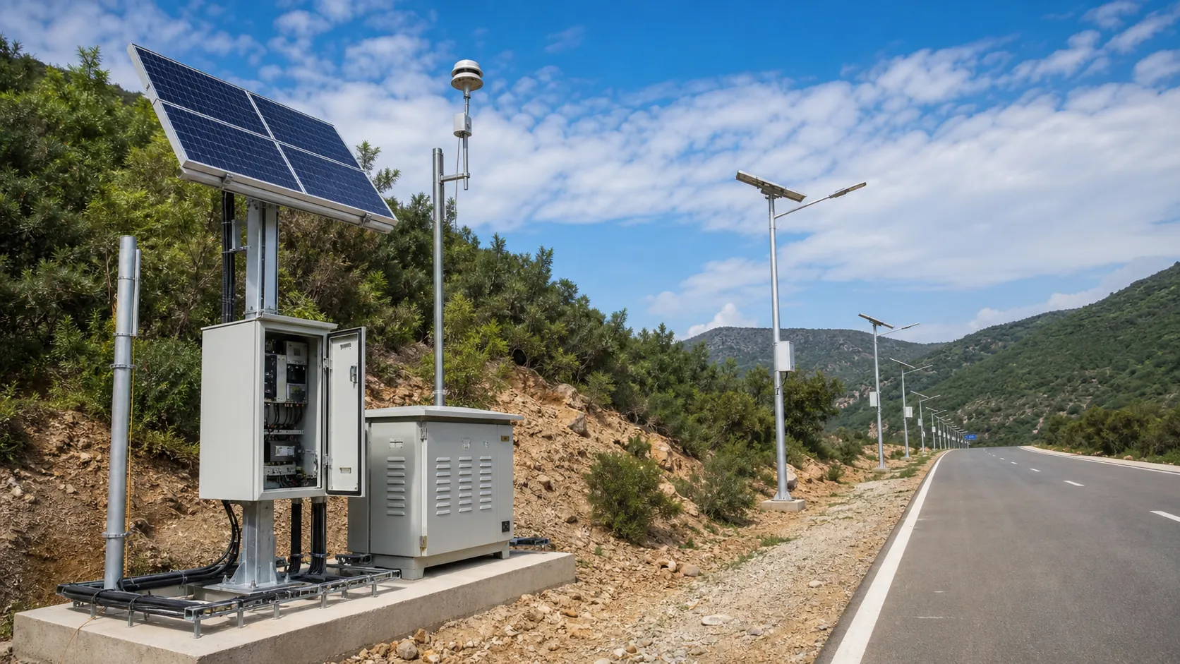
Design solar-powered outdoor IoT systems with panels, batteries, controllers, low-power devices, gateways and remote power monitoring.
Solar IoT Guide
A design guide for solar-powered outdoor IoT: load calculation, battery autonomy, low-power firmware, telemetry and maintenance planning.
Power and Connectivity
How to choose power, battery, solar, NB-IoT, LTE, LoRaWAN, gateways and monitoring strategy for outdoor IoT infrastructure.
Frequently Asked Questions
Can this EV charging station really run without any grid connection?
Yes. The RC-EVC-7040S is fully off-grid: solar panels charge a LiFePO4 battery bank through REDCOAST.LTD's custom MPPT power PCB, and the battery then powers EV charging.
How much battery storage does the station include?
Storage is configurable from 20 to 100 kWh of LiFePO4, sized to your expected daily charging demand and local solar conditions.
Does the station support OCPP for backend integration?
Yes. It supports OCPP 2.0.1, so it can connect to third-party charging networks and billing backends.
Where is an off-grid solar EV charging station most useful?
Sites with no grid connection or where trenching and grid-extension costs are high — remote parking areas, scenic sites and new lots awaiting grid service.
How is the station monitored and managed remotely?
IoT remote management is built in, so operators can supervise charging sessions, battery state and system health remotely through the management platform.
Can REDCOAST.LTD customize the station configuration?
Yes. REDCOAST.LTD delivers it as an end-to-end project — solar array size, storage capacity, charger output and software are engineered per site.
Does installation require civil works like cable trenching?
No grid connection or cable trenching is required, which shortens installation time and avoids grid-extension permitting.