Overview
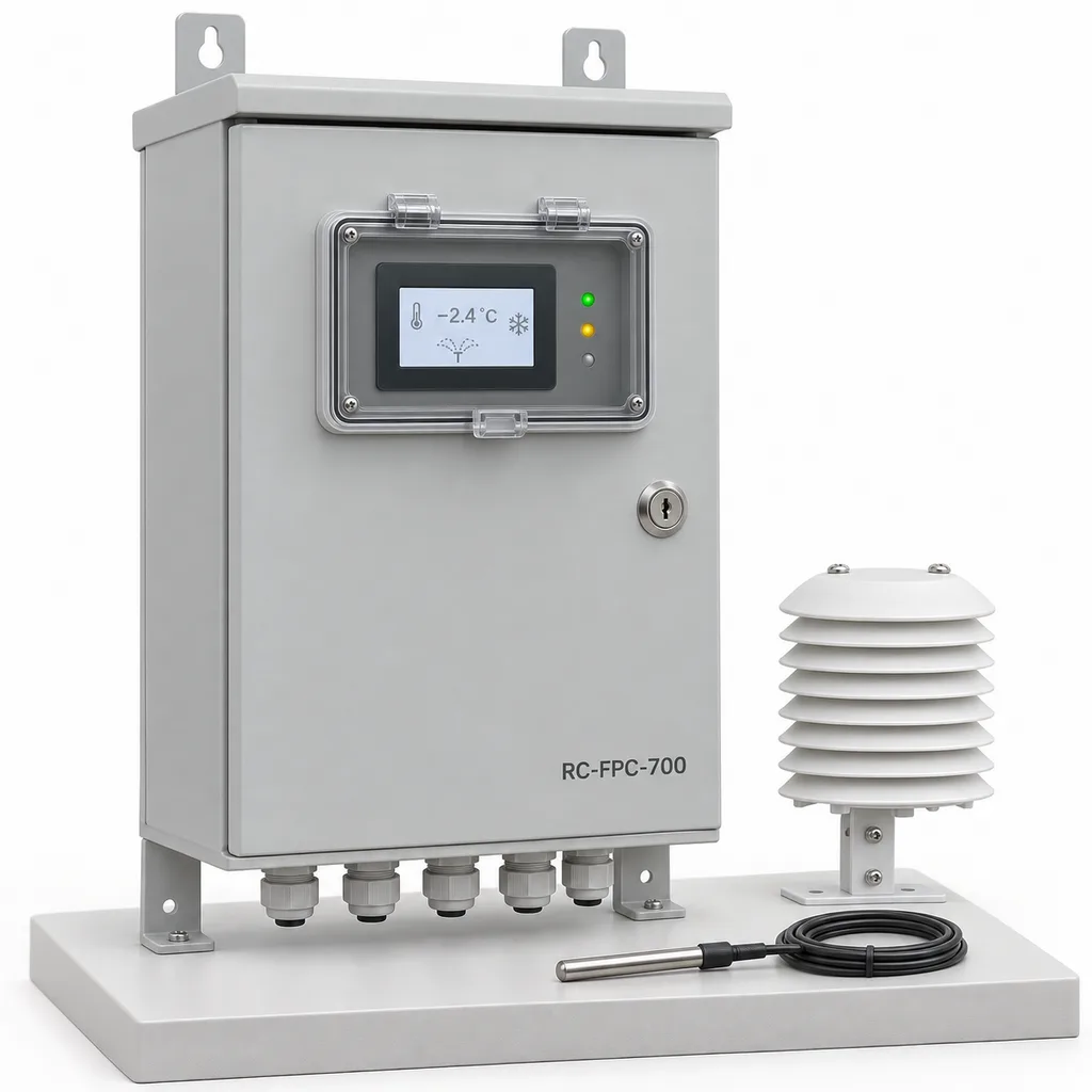
The RC-FPC-700 is a mains-powered orchard frost protection irrigation control station from REDCOAST.LTD, combining field sensing, local pump and valve control, a Web management platform, and a mobile app. It is intended for orchards, vineyards, berry farms, and outdoor nurseries with an established electricity supply and a hydraulically designed sprinkler protection system. Its purpose is to coordinate timely operation, verify that water is actually reaching the protected blocks, and alert operators when conditions or equipment depart from the agreed operating plan. REDCOAST.LTD develops the control electronics and custom PCBs as part of the complete solution, allowing the station to match existing pump starters, sensors, and valve arrangements. The specifications below define a proposed made-to-order reference configuration; final performance, environmental ratings, and conformity evidence are established for the ordered hardware through engineering and acceptance testing.
Key Features
- Frost-specific operating mode: coordinates monitoring, arming, pre-start checks, protection operation, and release using a commissioned crop and hydraulic operating plan.
- Four temperature measurement channels: compares representative crop blocks and cold pockets instead of relying on one sensor beside a warm pump house.
- Wet-bulb calculation: combines air temperature, humidity, and atmospheric pressure, with clear quality flags and separate display of measured and calculated values.
- Eight supervised valve outputs: drives compatible 24 V DC solenoids, monitors electrical faults, and verifies hydraulic response using pressure and flow feedback.
- Pump readiness supervision: accepts starter status, trip, water availability, and standby-source signals before issuing low-voltage run requests.
- Local control during network outages: retains the commissioned operating program and event history when Ethernet or cellular service becomes unavailable.
- Operator escalation: combines a local beacon and sounder with app notifications, acknowledgement records, and configurable escalation to additional authorized users.
- Project-specific board design: adapts analog front ends, isolated interfaces, output stages, terminal layouts, and firmware to the installation.
Technical Architecture
The reference package contains an outdoor control cabinet, four wired temperature probes, a humidity and air-temperature sensing position, a barometric sensor, a wind sensor, and hydraulic monitoring interfaces. REDCOAST.LTD designs the main controller PCB, precision RTD acquisition circuitry, isolated 4–20 mA interfaces, protected valve-driver PCB, and power-distribution monitoring circuitry. Industrial sensors, an appropriately approved AC/DC supply, protective devices, and pump motor starters are selected to complement these boards. The cabinet issues commands to external starters or VFD control inputs; it does not carry motor power through the controller PCB.
The local controller executes an explicit operating sequence. In monitoring mode it validates sensor freshness and compares block conditions; arming requires a locally approved configuration and an authorized operator action. Before starting, it checks water-source availability, pump readiness, and the combination of blocks that the hydraulic system can supply simultaneously. During protection, it compares commands with valve electrical status, flow, and pressure. A normal irrigation rain delay, soil-moisture inhibit, or cloud schedule must not inadvertently interrupt an active frost program. The final cause-and-effect matrix distinguishes an advisory alarm, a failed sensor, a hydraulic problem, and a protective pump trip; these conditions do not all receive the same response.
Measurements and events are stored locally and forwarded to the platform with timestamps and quality indicators. Operators can review block trends, inspect pressure loss, acknowledge an alarm, and compare the requested valve state with measured water delivery. Configuration changes are versioned, and remote commands expire rather than executing unexpectedly after a long communications outage. Release from protection follows the commissioned wet-bulb trend, persistence period, and operator permissions; sunrise or a positive dry-bulb reading alone is insufficient. This approach reflects the start-and-stop principles in FAO's frost protection guidance.
Connectivity & Power
The cabinet accepts AC 100–240 V, 50/60 Hz, from the farm or nursery electrical distribution system. An isolated 24 V DC, 240 W supply serves the controller, sensors, compatible valve coils, and cabinet auxiliaries. The reference input allowance is 250 W maximum with the specified loads, while the controller and communications electronics alone are budgeted at 12–20 W. Pump motors require their own correctly sized feeders, starters, protection, and energy budget. The station has no solar panel and makes no independent power-autonomy claim.
Ethernet is the standard backhaul where the pump house has a managed network; an optional LTE Cat 1 modem serves installations with suitable cellular coverage. Two isolated RS-485 ports support compatible Modbus RTU instruments, while 4–20 mA and pulse inputs accommodate common pressure transmitters and flow meters. Exposed field runs require appropriate cable routing, surge protection, grounding, and voltage-drop calculations. Fiber links or locally powered remote I/O are preferable for long routes between electrically separate buildings.
Loss of internet connectivity does not stop the local program. Loss of mains is different: without an independently engineered standby supply, both electronic control and electrically driven pumping can stop. Where continuity is required, the project must size and test a standby source for the complete pumping and control load. A small communications backup alone cannot maintain sprinkler protection.
Protection & Reliability
The cabinet design targets IP66 with the door closed and the specified glands, seals, and accessories fitted. The reference enclosure is hot-dip galvanized steel with a smooth matte RAL 7035 powder-coated topcoat; exposed mounting brackets receive the same finished coating system. A shaded location, an external rain hood, sealed cable entry, conformal coating on appropriate PCB areas, and a thermostatic 40 W anti-condensation heater address typical outdoor installation conditions. The heater controls cabinet moisture; it is not intended to heat an orchard or prevent exposed pipework from freezing.
The reference cabinet ambient range is -20 to +50 °C in a shaded installation. Solar loading, salt exposure, fertilizer aerosols, and persistent condensation are reviewed separately; coastal projects can specify an enhanced fluorocarbon topcoat and appropriate fasteners. Wind loading is assessed for the actual pedestal, sensor mast, and foundations rather than inferred from the enclosure rating. Temperature probes, filters, valve coils, seals, and surge devices remain serviceable components with inspection intervals defined in the maintenance plan.
Sensor icing, a disconnected probe, an implausible humidity value, and stale communications are identified as faults rather than silently treated as normal readings. A local Hand/Off/Auto arrangement at the pump starter provides an agreed manual operating path while preserving motor and electrical protections. Seasonal inspection and recorded functional checks support dependable operation; no fixed crop-survival temperature or untested service-life guarantee is claimed.
Application Scenarios
- Commercial fruit orchards: Install the cabinet beside an existing grid-fed pumping station and place sensors at representative flowering height and known cold pockets. Operators gain a coordinated view of frost conditions and water delivery across the selected protection blocks.
- Vineyard frost protection networks: Connect dedicated overhead frost sprinklers and monitor pressure at the hydraulically disadvantaged end of the network. The station helps identify a failed valve or insufficient supply that might otherwise remain unnoticed during overnight operation.
- Outdoor berry production: Associate low-level temperature measurements with the actual planting beds and verify the sprinkler application pattern during commissioning. A documented release procedure helps operators avoid stopping solely because the air feels warmer after sunrise.
- Container nurseries and propagation yards: Separate frost protection priorities from ordinary irrigation and fertigation schedules. Staff can monitor water-source availability and receive alarms without repeatedly visiting every manifold.
- Agricultural research and demonstration estates: Log crop-block temperature, operating commands, and hydraulic response through the same platform. Exportable records support comparison of operating strategies without presenting the controller as a substitute for agronomic evaluation.
Case-style Examples
The following are illustrative engineering scenarios, not reports of completed customer installations or measured crop-loss reductions.
Two-hectare orchard with an existing pump house. An operator has four 0.5 ha blocks and a suitable overhead sprinkler network but currently relies on manual overnight checks. A proposed package uses four temperature channels, four valve outputs, a mainline flow meter, two pressure transmitters, and Ethernet backhaul. If the independently selected application rate is 4 mm/h over all 2 ha, the delivered water demand is 80 m³/h, or 800 m³ for a ten-hour event before allowances for reserve and unusable storage. The intended operational result is simultaneous visibility of block conditions and confirmed flow; the controller cannot compensate for a source or pump that cannot meet this demand.
Nursery with intermittent cellular coverage. A grid-connected nursery wants to protect several outdoor growing areas while retaining its existing motor starter and hydraulic equipment. The proposed station uses LTE for remote supervision, local logging, wired sensors, starter feedback, and an on-site sounder, with the approved program stored in the controller. During a cellular outage, the local sequence would continue while records wait for upload, and staff would still have local controls. Acceptance testing would demonstrate communications loss, low-pressure response, manual operation, and recovery before the system is entrusted with an overnight frost event.
Customization & Selection Guide
Begin with the crop, growth stage, protected area, expected frost conditions, sprinkler type, and sustainable water supply. Overhead full-cover, individual-plant, and under-tree methods have different hydraulic and agronomic requirements; they cannot share an assumed universal precipitation rate or protection limit. Rivulis's frost protection guide describes these different approaches. This reference configuration focuses on a properly engineered overhead system, with all required blocks supplied continuously during protection. Strong wind, inadequate wetting, or an interrupted water supply can defeat the intended protection; the operating envelope must therefore be established for the actual installation.
Select the number of valve circuits from the hydraulic layout, not simply the number of field names on a map. The eight electrical outputs can operate together within their current budget, but eight outputs do not establish an eight-block hydraulic capacity. Conventional overhead frost irrigation must not be converted into ordinary sequential watering merely to fit an undersized pump. Any specialized pulsed-emitter approach requires the emitter manufacturer's design method and separate validation; the controller does not promise generic water savings.
Sensor selection should reflect the risk and the site. Place an upwind reference outside sprinkler wetting, and add representative crop-height probes in colder areas. The base humidity option has stated accuracy under defined non-condensing conditions; installations that regularly approach saturation can specify a warmed humidity probe with a separate ambient-temperature sensor. Such separation matters because warming changes the sensing element's temperature, as explained in Vaisala's warmed-probe documentation.
For procurement, identify cabinet location, cable lengths, existing coil voltages, pump control interfaces, water storage, remote-access policy, and the required acceptance tests. Existing 24 V AC valves require the corresponding isolated AC driver option; they must not be connected to the standard DC outputs. Mechanical pump protection, water-source limitations, and sprinkler suitability are reviewed before automatic operation is enabled.
Deployment & After-sales
Deployment starts with a site survey and an agreed I/O schedule, hydraulic operating envelope, alarm matrix, and crop-specific activation and release procedure. The cabinet mounts on a wall or finished pedestal above foreseeable standing water. Installation includes protective earthing, segregated mains and instrument wiring, sensor positioning, flow-meter setup, and identification of every valve and pump feedback signal.
Factory acceptance should verify analog inputs, output loading, sensor-fault handling, command expiry, configuration retention, and communications-loss behavior. Site acceptance then checks actual sprinkler delivery, representative pressure, source capacity, alarm routing, manual operation, and any standby-power transfer. Hydraulic tests must cover the intended simultaneous block combination. Software simulation alone does not establish frost protection performance.
For project planning, an initial custom pilot can be scoped around an indicative 8–12-week engineering and assembly window after requirements and component availability are confirmed; the quotation establishes the actual schedule. Delivery documentation should include wiring drawings, terminal schedules, the approved program, configuration backups, commissioning records, and maintenance instructions. After-sales arrangements cover remote diagnostics, replacement boards and probes, seasonal functional checks, and agreed firmware support. Warranty duration, service response, and calibration responsibilities are specified in the supply contract.
Standards & Compliance
The qualification plan should address enclosure protection under IEC 60529, electrical safety under IEC 61010-1 with any applicable particular requirements, and measurement/control EMC under IEC 61326-1:2020. Platinum sensor element characteristics can be specified against IEC 60751:2022; element tolerance does not establish installed system accuracy.
The ordered configuration determines applicable radio approvals, restricted-substance documentation, and market-specific conformity assessment, including CE marking where relevant. A pre-approved modem or power supply does not certify the complete cabinet. IP66 and temperature values on this page are design targets until supported by the final assembly's verification records; no certification badge or test report is implied.
Technical background also includes the sensor and hydraulic feedback categories in Netafim's May 2025 sensor catalog. Agricultural operating limits follow the selected crop, emitters, weather, and water supply. FAO's sprinkler frost-protection analysis provides the physical basis for evaluating evaporation, freezing, application rates, and operating conditions; these references inform engineering and are not product certification evidence.
Why REDCOAST.LTD
REDCOAST.LTD delivers the station as one coordinated hardware, firmware, Web platform, and mobile-app solution. In-house development includes new PCB layouts and board-level design for the sensor front ends, isolated interfaces, valve outputs, and cabinet control functions when the project requires them. This makes it possible to match legacy hydraulic equipment, add meaningful diagnostic signals, and maintain a documented relationship between field wiring, controller behavior, and the operator interface.
The result is a defined product that can be adapted to the installation, with component selection, acceptance criteria, and support scope agreed before deployment. Pumps, sprinklers, and specialist sensing elements are selected according to their verified capabilities, while REDCOAST.LTD owns the integration and custom electronic control design.
Contact REDCOAST.LTD with your crop blocks, sprinkler layout, pump curves, water-source capacity, and preferred connectivity to request a tailored RC-FPC-700 proposal.
Specifications
Control & Outputs
- Controlled valve circuits
- 8 independently addressed; simultaneous operation within electrical and hydraulic limits channels
- Standard valve supply
- 24 DC; non-latching solenoid coils V
- Valve output current
- 0.5 continuous per channel; 4 total; coil inrush subject to selection A
- Pump run-request contacts
- 2 dry-contact outputs, 30 V DC / 1 A resistive maximum; external starter interface
- Operating modes
- Monitor, Manual, Armed, Protection, Release, Fault
- Local display
- 4.3-inch HMI behind a sealed access door
- Configurable alarm persistence
- 5–300; assigned by fault type s
Temperature & Weather Sensing
- Temperature inputs
- 4 channels, 4-wire Pt100
- Temperature measurement span
- -30 to +60 °C
- Temperature channel accuracy target
- ±0.3 over -10 to +10 after probe-and-channel calibration °C
- Relative humidity measurement
- 0–100; ±2 accuracy target at +15 to +25 °C and 10–90 %RH, non-condensing %RH
- Atmospheric pressure measurement
- 600–1100; ±1 accuracy target at +20 °C hPa
- Wind speed measurement
- 0–40; ±0.5 or ±5% of reading, whichever is greater, without icing m/s
- Derived frost variables
- Dew point and wet-bulb temperature calculated from validated inputs; 0.1 °C display resolution
Hydraulic Monitoring & Field I/O
- Analog acquisition
- 8 inputs, 4–20 mA; ±0.2% full-scale acquisition target at +25 °C channels
- Pressure transmitter selection
- 0–10 or 0–16; ±0.5% full-scale target at +20 °C bar
- Flow-meter pulse inputs
- 2; 0–100 Hz input frequency channels
- Digital status inputs
- 16 optoisolated, 24 V DC channels
- Pressure process connections
- G1/4 or 1/4-inch NPT; matched to the selected transmitter
- Water-delivery verification
- Flow pulse totalization, mainline pressure, remote pressure, pump run/trip, source-level contact
- Motor power switching
- External motor starter or VFD; no direct motor-power output
Grid Power
- Input voltage
- AC 100–240 V
- Input frequency
- 50/60 Hz
- Internal isolated supply
- 24 V DC, 10 A, 240 W nominal
- Controller and communications load
- 12–20 reference budget; excludes field loads and heater W
- Maximum cabinet input allowance
- 250 with specified loads; pump motors excluded W
- External sensor power allowance
- 24 V DC, 1 A total
- Anti-condensation heater
- 40, thermostatically controlled W
- Beacon and sounder allowance
- 12 maximum combined W
Connectivity & Data
- Ethernet
- 1 × 10/100BASE-T port
- Cellular option
- LTE Cat 1; modem bands and carrier acceptance selected for installation
- RS-485
- 2 isolated ports; Modbus RTU, 9.6–115.2 kbit/s
- Platform connection
- MQTT over TLS 1.2 or later; HTTPS management API
- Acquisition and recording
- 1-second acquisition cycle; 10-second standard trend interval
- Local history allocation
- 30 days for 32 numeric channels at 10-second intervals, plus event records
- Management software
- Web dashboard, mobile app, role-based access, acknowledgement log, CSV export
Enclosure & Environment
- Cabinet protection target
- IP66, door closed and specified glands fitted; final assembly verification required
- Cabinet dimensions
- 600 × 400 × 200, height × width × depth; pedestal excluded mm
- Cabinet ambient target
- -20 to +50, shaded installation; final thermal qualification required °C
- Storage temperature target
- -30 to +70 °C
- Enclosure construction
- Hot-dip galvanized steel with smooth matte RAL 7035 powder-coated topcoat
- Mounting
- Wall brackets or 1000 mm finished pedestal
- Internal humidity envelope
- 10–95, non-condensing; external sensors have separate limits %RH
Capabilities — configurable per project
Specifications are tailored to each project — the options below show what we can support.
Frost sensing package
- Four wired Pt100 channels plus standard RH probe
- Warmed humidity probe with separate ambient-temperature sensor
- Additional crop-contact temperature probes through remote I/O
Valve and pump interfaces
- Eight 24 V DC non-latching valve outputs
- Isolated 24 V AC driver board for existing AC valves
- Dry-contact valve actuator interface with position feedback
- Pump VFD Modbus integration after register-map verification
Site communications
- Managed Ethernet backhaul
- LTE Cat 1 cellular backhaul
- Fiber-linked remote I/O with local mains supply
Software delivery
- Managed Web platform and mobile app
- Customer-hosted management server
- Documented API integration with an existing farm platform
Outdoor installation
- Powder-coated wall cabinet with rain hood
- Powder-coated pedestal cabinet
- Galvanized substrate with smooth fluorocarbon topcoat for corrosive exposure
Related solution guidance

Environmental Monitoring
Deploy environmental monitoring stations with sensors, solar power, gateways, dashboards, alarms and data integration for city and industrial sites.
Ports and Logistics
Outdoor IoT infrastructure for ports, yards and logistics areas: lighting, guidance, safety, solar power, monitoring and maintenance visibility.

Street Lighting Guide
A practical guide to choosing smart street lighting controllers, connectivity, platform features, dimming logic and acceptance tests.
Frequently Asked Questions
How does a frost protection controller differ from a normal irrigation timer?
A normal timer schedules watering, while the RC-FPC-700 coordinates a commissioned frost operating procedure using temperature, humidity, pressure, flow, and equipment status. Its frost mode is designed to prevent ordinary rain delays or moisture-based scheduling from unintentionally interrupting an active protection cycle. Crop thresholds and release rules must be established for the actual planting and sprinkler system.
Can the station reuse existing pumps, valves, and sprinklers?
Existing pumps and compatible control interfaces can be retained after checking the pump curve, simultaneous flow demand, pressure losses, and protective devices. Standard outputs are for 24 V DC non-latching coils; 24 V AC coils require the corresponding AC driver option. Existing drip irrigation alone does not provide the overhead wetting pattern assumed by this reference design.
How much water does overhead frost protection require?
Required application depends on the crop, sprinkler arrangement, temperature, humidity, and wind; there is no universal rate. For a sizing example only, 4 mm/h over one hectare equals 40 m³/h, so ten hours requires 400 m³ delivered to that area before reserve allowances. The water source, pipes, and pumps must sustain the independently selected application rate throughout the protection period.
Will frost control continue if the internet or electricity fails?
The locally stored program can continue when internet access fails, provided the controller, sensors, valves, and pumps remain powered and healthy. A mains outage can interrupt protection because this configuration does not include independent energy storage. Continuity requires a separately engineered and tested standby source sized for the complete pumping and control load.
Does the RC-FPC-700 guarantee protection down to a specified temperature?
No universal crop-protection temperature is specified. Results depend on plant growth stage, wetting uniformity, sustained application, wind, humidity, water availability, and the type of frost. The cabinet operating-temperature range describes the electronics environment and must not be interpreted as a crop-protection rating.
Does REDCOAST.LTD design the hardware or only integrate purchased controllers?
REDCOAST.LTD develops the controller electronics, custom PCBs, sensor acquisition circuits, valve-driver boards, and project-specific firmware alongside the Web platform and mobile app. Specialist sensors, approved power supplies, and hydraulic components are selected from suitable suppliers where appropriate. New board layouts and interface changes are defined in the project scope and verified before delivery.
Are IP66 and the listed standards already certified for this model?
This product package describes a made-to-order reference design, with IP66 and environmental values stated as qualification targets. Certification, declarations, and test reports apply only to the final ordered configuration after the relevant assessment. Buyers should request the agreed compliance matrix and matching reports as part of the delivery documentation.
What information is needed for a tailored quotation?
Provide the crop and growth stages, block areas, sprinkler data, pump curves, available water volume, existing valve voltages, cable routes, and mains supply details. Also identify the required alarm recipients, preferred hosting arrangement, and any standby-power provision. REDCOAST.LTD can then define the I/O schedule, board modifications, commissioning scope, and commercial delivery terms.