Overview
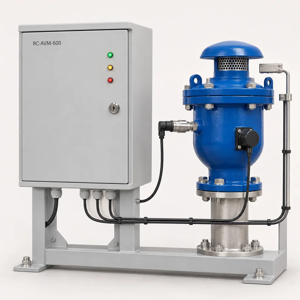
The RC-AVM-600 is a mains-powered air release valve condition monitoring station for irrigation operators, water utilities, industrial campuses and water infrastructure integrators. It combines pressure measurement, discharge wetness detection, contact-acoustic sensing and maintenance records to help teams investigate leaking or unusually operating air valves before the next routine inspection. REDCOAST.LTD delivers the station, field sensor assemblies, Web management platform and mobile application as one project-configured solution, with in-house PCB and board-level hardware development behind the sensing and control electronics. The reference package monitors one air valve and expands to four nearby valves, making it suitable for pump compounds, treatment sites and accessible valve chambers with an existing electrical supply. Specifications below define a proposed reference build and its acceptance targets; final ratings and performance require verification of the ordered configuration.
Key Features
- Valve-specific maintenance evidence: Combine operating pressure, venting-related vibration and discharge wetness on one timeline, helping technicians distinguish a persistent leak indication from a brief filling event.
- One-to-four-valve station: Start with one instrumented valve and add field assemblies without replacing the cabinet, asset database or operator interface.
- Custom sensing hardware: REDCOAST.LTD develops the analog acquisition PCB, acoustic sensor front end, protected field I/O and station controller around the selected sensors and installation conditions.
- Unobstructed mechanical operation: External mounting and approved existing pressure ports preserve the air valve's intake and discharge paths; no automatic shutoff device is inserted into the vent.
- Local decisions during Internet outages: Configurable persistence timers, local event storage and hardwired alarm contacts operate independently of the hosted platform while station power remains available.
- Maintenance-aware alarms: Tag commissioning, flushing and planned isolation periods, retain their history, and distinguish disabled monitoring from a healthy valve.
- Practical retrofit interfaces: Use 4–20 mA pressure transmitters, supervised contact inputs and isolated RS-485 sensor buses, with Ethernet or optional cellular backhaul.
- Auditable service workflow: Assign asset locations, acknowledge alarms, attach inspection photographs and compare operating signatures before and after cleaning or seal replacement.
Technical Architecture
A reference station contains a lockable above-ground cabinet, an AC-to-24 V DC supply, a deterministic I/O controller and an industrial gateway. Each monitored valve receives a pressure transmitter connected through an approved service port, a mechanically coupled acoustic pickup and a wetness probe positioned at an appropriate discharge collection point. A separate chamber flood switch provides context when surrounding water could explain a wet probe. The standard PCB arrangement provides four pressure inputs, twelve supervised contact inputs and four low-voltage alarm relay outputs; optional isolation-position switches and pump-running contacts use the assigned input budget. Pressure-bearing valve bodies remain selected mechanical components, while REDCOAST.LTD engineers the monitoring electronics, firmware and software integration.
The pressure channels acquire data at 10 samples per second and generate one-second trends. Acoustic nodes sample locally at 24 ksample/s, extract activity features and retain selected short waveform clips for engineering review; they do not stream continuous audio to the cloud. Configurable rules combine wetness duration, pressure state, pump status and the commissioned acoustic baseline. For example, persistent wetness during stable pressurization can raise a discharge-leak investigation alarm, while a change in venting activity can trigger a maintenance advisory. Rain, condensation, pipe-borne pump vibration and legitimate venting remain possible confounders. A quiet sensor alone does not prove blockage, and this system does not measure discharged air volume or certify the valve's remaining air-handling capacity.
The gateway timestamps observations, retains event context and forwards trends to the Web platform or an existing SCADA system. Users see separate states for measured conditions, suspected faults, sensor failure and missing communications; stale readings remain visibly stale. An installer establishes the baseline during observed filling, steady operation and shutdown, then checks that maintenance alarms correspond to useful field evidence. The monitoring principle has an established industry basis: A.R.I.'s ARISENSE literature describes air valve monitoring with pressure, leakage and chamber-flood sensing, while AES's published air valve investigation illustrates acoustic observations correlated with pump operation. These sources support the application and diagnostic approach, rather than validating this proposed station.
Connectivity & Power
The intended locations already have utility power: irrigation pump buildings, waterworks compounds, landscaped campuses and serviceable distribution sites. The cabinet accepts AC 100–240 V at 50/60 Hz and distributes protected 24 V DC to its electronics and wired field sensors. The one-valve reference configuration budgets 18–30 W during normal monitoring. The configured station has a 120 W maximum AC input allowance, including an optional 60 W anti-condensation heater; actual consumption depends on installed channels, communications and ambient conditions.
Ethernet is the preferred backhaul where a site network exists. Optional 4G LTE provides an independent connection or backup path, with the modem bands and SIM selected for the installation country and operator. Fiber can be provided through an industrial switch for electrically noisy or separated buildings. Field RS-485 and pressure-loop cables use shielded routes, appropriate surge protection and a cable-specific voltage-drop check. The normal reference layout places sensors within 100 m cable distance of the cabinet; longer runs require a revised power and communications design.
Local alarms continue through a backhaul outage, and buffered records upload after service returns. A mains failure stops monitoring unless the site supplies an externally backed-up circuit; the platform identifies the resulting missed heartbeat. Neither solar panels nor an internal battery pack form part of this configuration. Alarm relays provide status to a supervisory controller, with any pump-stop action designed and commissioned separately.
Protection & Reliability
The cabinet targets IP66 protection, using a hot-dip-galvanized steel substrate, suitable surface preparation and a smooth matte powder-coated exterior. Field sensing assemblies target IP68 protection for 1 m immersion over 24 hours with their specified cables and seals. These are assembly-level qualification targets, not a claim that an entire installation can operate indefinitely underwater. Pressure-reference vents, where required, terminate above the flood level.
The standard cabinet ambient target is -10 to +50 °C, with a heater-equipped package for assessment down to -20 °C. Water-filled instruments require separate freeze protection, and the reference wetted equipment is selected for liquid temperatures of +1 to +50 °C. Hot sites need a sunshade and a confirmed internal thermal budget. Coastal sites require an agreed coating system, suitable fasteners and inspection access; IP protection alone does not establish corrosion resistance. Cable glands, sealing surfaces and cabinet anchors are checked against dust exposure, flooding elevation and the site's wind conditions.
Replaceable power supplies, pluggable terminals, watchdog recovery and separate sensor-health reporting make faults easier to isolate. Commissioning and maintenance include wet-probe tests, pressure checks, cable supervision tests and inspection of mounting stiffness. Warranty scope, spare-part availability and service intervals are defined in the project agreement, with calibration and consumable seals treated explicitly.
Application Scenarios
- Irrigation pump compounds: Monitor combination air valves near pump discharge manifolds and elevated pipe sections within the powered compound. Correlating vent activity with irrigation cycles helps maintenance teams investigate recurrent leakage or changed operation without adding another irrigation scheduler.
- Water treatment and storage sites: Instrument air valves on treated-water transfer lines, reservoir connections and accessible service galleries. Operators can view valve-specific alarms alongside pump and tank status, then dispatch a technician with relevant pressure and wetness history.
- Industrial campus water networks: Cover clustered air valves serving cooling-water or nonhazardous utility-water loops. Asset-specific evidence helps separate a local valve maintenance issue from changes in the wider pumping schedule.
- Reclaimed-water landscape supply: Monitor air valves at powered distribution hubs supplying parks, sports grounds or landscaped estates. Discharge wetness and event history help prioritize inspections where recurring deposits or maintenance access make calendar-only visits inefficient.
- Municipal distribution retrofit sites: Add monitoring to suitable existing air valve assemblies near an electrical service point. Above-ground electronics and accessible test connections support inspection without turning every routine data check into a chamber entry.
Case-style Examples
The following examples are illustrative configurations, not claims of completed REDCOAST.LTD installations or measured savings.
Irrigation pump-house maintenance upgrade. An operator has two combination air valves and receives occasional reports of water around their discharge areas after irrigation cycles. A two-valve station uses individual pressure, wetness and acoustic channels, together with pump-running contacts and a chamber flood switch. During commissioning, the team observes normal filling and agrees a persistent-wetness alarm delay. The intended outcome is a time-stamped inspection record that helps distinguish a valve-discharge issue from chamber flooding, with savings evaluated from actual site data.
Campus water-network retrofit. A facilities team wants visibility of four air valves grouped around a powered utility building. A four-valve cabinet connects by Ethernet to the existing operations network and exports alarm states to SCADA, while maintenance staff use the mobile application for photographs and work completion. Initial inspections establish valve condition and acoustic mounting quality. The proposed workflow links each advisory to its supporting measurements and records whether cleaning or seal replacement changes the observed behavior.
Customization & Selection Guide
Begin with the valve inventory: manufacturer, model, nominal diameter, pressure class, liquid, existing service ports, vent arrangement and isolation access. The reference installation envelope covers DN25–DN100 air valve assemblies, but compatibility depends on geometry and approved connections rather than diameter alone. Send photographs and drawings so sensor clamps and wetness detection can be arranged without obstructing ventilation, adding backpressure or compromising sanitary protection.
Choose a pressure range that covers normal operation and the specified transient envelope, while keeping useful resolution. Reference options are 0–10, 0–16 and 0–25 bar gauge; a -1 to +15 bar compound transmitter is an alternative for low-pressure and vacuum observations. A gauge-only 0–16 bar transmitter cannot characterize vacuum, and the 10 Hz acquisition is not a dedicated water-hammer recorder. Pressure accuracy is specified at reference temperature and must be reviewed over the actual environment. WIKA's February 2026 A-10 datasheet illustrates the distinction between non-linearity, total measured error and additional temperature effects.
For a constrained budget, prioritize pressure, discharge wetness and reliable communications at the most troublesome valve. Add acoustic channels where repeatable mounting and operational baselines make them useful, and add isolation-position switches where accidental closure is a known maintenance concern. Choose an on-premises deployment when the operator requires local data custody. Define retention, user roles, alarm routing and integration responsibilities before ordering; estimated savings should follow a monitored baseline rather than a generic percentage claim.
Deployment & After-sales
Deployment starts with a site survey, sensor schedule and cabinet location above the design flood elevation. Qualified personnel isolate and depressurize pipework before fitting pressure connections, confirm the valve manufacturer's installation requirements, and verify that the vent remains unobstructed. Mount acoustic sensors consistently, route wetness probes away from unrelated runoff, and verify pressure-loop calibration before establishing an operating baseline.
Factory acceptance should exercise input ranges, contact supervision, loss of communications, restart behavior, local alarms and data recovery. Site acceptance adds observed valve operation, controlled wet-probe tests, cellular or Ethernet checks and operator training. Delivery planning separates drawing approval, any new PCB development, prototype verification, procurement and final assembly; the quotation confirms dates after component and testing requirements are agreed.
The handover package includes wiring diagrams, sensor locations, configuration backups, calibration records where supplied, alarm definitions and service instructions. Remote support can review event records with the customer's authorization, while replacement sensor assemblies use documented recommissioning procedures. Firmware updates, access roles and audit logs are included in the software scope, with maintenance notifications and escalation contacts configured for the operator's workflow.
Standards & Compliance
The enclosure qualification plan references IEC 60529 for ingress protection. Electrical safety assessment considers IEC 61010-1, and electromagnetic compatibility assessment considers IEC 61326-1:2020 for measurement and control equipment. The applicable editions, installation environment and test configuration are agreed for the supplied assembly.
Mechanical air valve selection remains a separate engineering responsibility. AWWA's current standards list includes C512-25 for air-release, air/vacuum and combination air valves for water and wastewater service; adding monitoring electronics does not certify an existing valve to that standard. Potable-water projects also require appropriate acceptance of wetted materials and preservation of hygienic vent arrangements.
Destination-specific electrical, radio and substance requirements are reviewed for the ordered configuration. Any CE marking, radio approval, material declaration or test certificate must correspond to the delivered equipment; this reference product description does not claim completed certification. The standard station is intended for nonhazardous locations, and classified atmospheres require a separately assessed equipment package.
Why REDCOAST.LTD
REDCOAST.LTD brings the field hardware, embedded firmware, Web platform and mobile maintenance tools into one coordinated delivery scope. Its in-house PCB and board-level design capability allows pressure acquisition, acoustic conditioning, supervised inputs, power distribution and connector arrangements to match the actual valve installation. That flexibility matters when an operator needs an unusual sensor combination, a constrained cabinet layout, a specific SCADA interface or a gradual retrofit across mixed assets.
The project can therefore be specified around a practical maintenance question: which valve needs attention, what evidence supports that decision, and how will the result be recorded after service? REDCOAST.LTD can tailor the electronics and software to that workflow while retaining explicit limits on diagnostic certainty and project-specific verification.
Contact REDCOAST.LTD with your air valve inventory, pressure ranges, site photographs and integration requirements to configure an RC-AVM-600 monitoring solution.
Specifications
Monitoring & Field Interfaces
- Monitored air valves
- 1 in reference kit; expandable to 4 valves
- Reference valve installation envelope
- DN25–DN100; mounting and port compatibility checked per valve model
- Pressure inputs
- 4 × 4–20 mA channels
- Pressure transmitter ranges
- 0–10 / 0–16 / 0–25 gauge; -1 to +15 compound bar
- Pressure measurement acceptance target
- ±1.0% of span including input channel, at 23 ±5 °C; temperature effects additional
- Process connections
- G1/4 or 1/4 NPT, selected to match approved service port
- Supervised contact inputs
- 12; assigned across leak, flood, isolation-position, door and pump-status signals channels
- Alarm relay outputs
- 4 dry contacts, each rated 1 A at 30 V DC for resistive loads
Acquisition & Alarm Logic
- Pressure acquisition rate
- 10 per input samples/s
- Pressure trend interval
- 1 s
- Contact-acoustic channels
- 1 in reference kit; expandable to 4 channels
- Acoustic digitization
- 24 ksample/s, 16-bit, local processing
- Acoustic feature band
- 100–8,000 Hz
- Local acoustic event clip duration
- 2–10; retrieved on demand, no continuous audio streaming s
- Alarm persistence timer
- 5–300; reference setting 30 s
- Alarm classification
- Persistent discharge wetness; pressure threshold; acoustic deviation; sensor fault; communications loss
Grid Power
- AC input voltage
- 100–240 V AC
- Input frequency
- 50/60 Hz
- Field supply output
- 24 V DC; 24 W aggregate external field-load limit
- Reference kit consumption
- 18–30; one valve, Ethernet, heater off W
- Maximum configured AC consumption
- 120; includes optional heater and selected field devices W
- Optional cabinet heater
- 60; thermostatically controlled W
Connectivity & Data
- Ethernet
- 2 × 10/100BASE-T ports
- Field serial buses
- 2 isolated RS-485; 9,600–115,200 bit/s ports
- Reference sensor cable distance
- Up to 100, subject to cable voltage-drop and EMC review m
- Optional cellular backhaul
- 4G LTE Cat 1 or Cat 4 modem; country-specific band selection
- Integration protocols
- Modbus RTU; Modbus TCP; MQTT over TLS 1.2/1.3; HTTPS REST API
- Local industrial storage
- 32 GB
- Trend retention allocation
- 90 days at 1-second intervals for four pressure channels plus event metadata; waveform storage separately capped
- Cloud trend upload interval
- 10–300; alarms sent when qualified and connectivity is available s
Mechanical & Environmental
- Reference cabinet dimensions
- 600 × 450 × 250, height × width × depth mm
- Cabinet construction
- Hot-dip-galvanized steel with prepared substrate and smooth matte powder coating, RAL 7035
- Cabinet ingress qualification target
- IP66, complete assembled cabinet
- Field assembly ingress qualification target
- IP68, 1 m immersion for 24 h, specified cables and seals fitted
- Cabinet ambient target
- -10 to +50; -20 lower limit with heater package and thermal qualification °C
- Reference liquid temperature
- +1 to +50; no freezing in wetted instruments °C
- Mounting arrangement
- Wall bracket or ground plinth; cabinet above design flood elevation
Software & Maintenance
- Deployment options
- Hosted platform; on-premises server; existing-SCADA integration
- Operator interfaces
- Browser dashboard; Android app; iOS app
- Access roles
- Viewer; operator; maintenance technician; administrator
- Alarm delivery
- Dashboard; mobile push; email; hardwired relay
- Data export
- CSV event and trend exports; JSON REST API
- Commissioning baseline period
- 7–14 days suggested, including observed filling, steady operation and shutdown
- Initial inspection schedule
- 3-month visual and functional checks; 12-month pressure verification, adjusted to site findings
Capabilities — configurable per project
Specifications are tailored to each project — the options below show what we can support.
Monitoring package
- One-valve pressure and discharge-wetness kit
- Two-valve kit with contact-acoustic sensing
- Four-valve kit with acoustic and isolation-position monitoring
Pressure measurement
- 0–10 bar gauge
- 0–16 bar gauge
- 0–25 bar gauge
- -1 to +15 bar compound
Backhaul
- Ethernet
- Ethernet with 4G LTE failover
- Fiber through an industrial Ethernet switch
Software deployment
- Hosted Web platform and mobile app
- On-premises platform and mobile app
- Existing SCADA with Modbus TCP and REST API
Environmental package
- Standard outdoor cabinet
- Cold-climate cabinet with 60 W heater and protected instruments
- Coastal coating system with corrosion-resistant fasteners
Related solution guidance

Environmental Monitoring
Deploy environmental monitoring stations with sensors, solar power, gateways, dashboards, alarms and data integration for city and industrial sites.
Power and Connectivity
How to choose power, battery, solar, NB-IoT, LTE, LoRaWAN, gateways and monitoring strategy for outdoor IoT infrastructure.

Airports and Hubs
IoT infrastructure for transport hubs: parking guidance, road safety, outdoor lighting, signage, monitoring and operational dashboards.
Frequently Asked Questions
Can the RC-AVM-600 retrofit existing air release and combination air valves?
Yes, where the existing valve provides suitable mounting geometry and an approved pressure connection. The reference design covers DN25–DN100 assemblies, but diameter alone does not establish compatibility. REDCOAST.LTD reviews the valve model, vent layout and photographs before defining the sensor kit; pressure bodies are not drilled or modified as a standard installation step.
Can it confirm that an air valve is blocked or measure the volume of discharged air?
It provides pressure, wetness and acoustic evidence for maintenance decisions, but does not directly measure air volume or certify vent capacity. Reduced acoustic activity can result from normal operating changes as well as a fault, so an advisory requires comparison with the commissioned baseline and operating context. Confirming blockage or mechanical condition requires inspection or a separately specified functional test.
How does the station distinguish air valve leakage from rain or chamber flooding?
A dedicated wetness probe is positioned at a suitable discharge collection point, while a separate flood switch monitors surrounding water. The controller combines these signals with pressure, pump status and an adjustable persistence delay. The result remains a leak investigation alarm rather than proof of a specific failed seal, and the probe layout must be checked for condensation and unrelated runoff.
Why is this configuration mains-powered, and what happens during an outage?
It is intended for pump compounds, treatment sites and campus utility areas with an existing AC supply, where continuous sensing and wired interfaces are practical. It accepts AC 100–240 V and includes no solar array or internal battery pack. Local monitoring continues during an Internet outage, but stops during a mains outage unless the installation uses an externally backed-up supply.
Can it work with an existing SCADA system without a hosted cloud subscription?
Yes. The station can expose agreed measurements and alarms through Modbus TCP, while serial field devices use Modbus RTU where applicable. An on-premises platform or direct SCADA integration can provide the operating interface; tag maps, alarm ownership, retention and API scope are defined during configuration.
Does an alarm automatically shut the air valve or stop the pump?
The reference station monitors conditions and provides alarm contacts; it does not close the air vent. Blocking an air valve can interfere with its required air-release or vacuum-admission function. A pump-stop or isolation sequence, if required, must be separately engineered with the hydraulic controls and verified during commissioning.
Is the station suitable for potable water, wastewater and hazardous chambers?
Potable-water installations require accepted wetted materials and a sensor arrangement that preserves hygienic ventilation. The standard package is for nonhazardous water and reclaimed-water installations. Wastewater chemistry, fouling and any classified atmosphere require a separate assessment and an appropriate sensor and electrical package; the reference station does not claim explosion-protection certification.
What information is needed for a reliable quotation and diagnostic configuration?
Provide valve models and sizes, pressure and liquid-temperature ranges, site photographs, available service ports, sensor cable distances and AC supply details. Include the pump operating sequence, known leakage history, flood exposure and the required SCADA or platform interface. These inputs determine sensor placement, channel allocation, enclosure treatment, testing scope and delivery schedule.