Overview
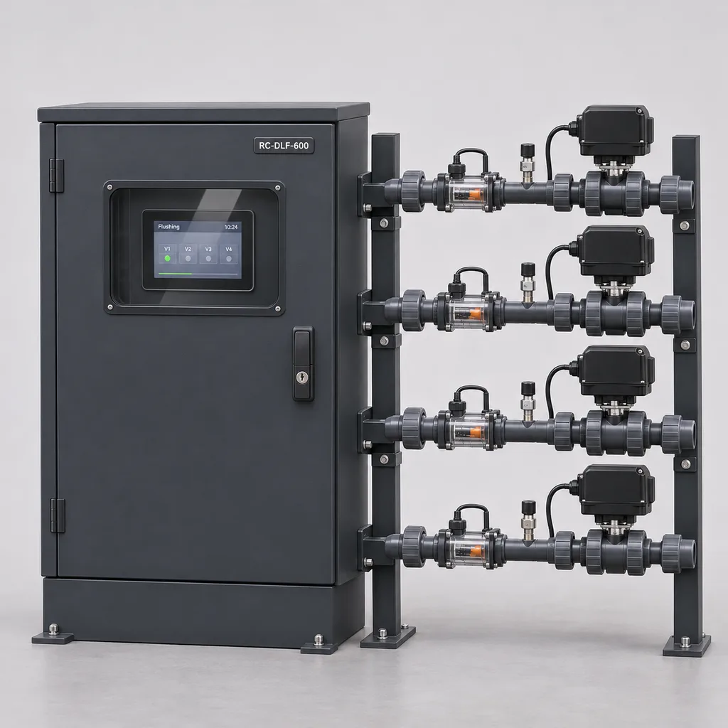
The RC-DLF-600 is a mains-powered automatic drip irrigation flushing and end-of-line monitoring station from REDCOAST.LTD, supplied as an integrated package of field hardware, local controls, a Web management platform and a mobile App. It serves municipal landscape teams, campuses, commercial estates and irrigation contractors maintaining permanent dripline networks. Four or eight instrumented flushing groups replace repeated manual opening of lateral-end valves with scheduled, measured maintenance cycles and exception reporting. REDCOAST.LTD develops the controller, sensor-interface and actuator-supervision PCBs in-house, allowing the complete system to fit the project's pipework, operating procedures and existing irrigation controls.
Key Features
- Four or eight measured flushing groups: Each group has its own motorized flush valve, discharge flowmeter and end-of-line pressure sensor, making maintenance records traceable to a specific irrigation block.
- Sequential operation: Only one flushing group operates at a time, limiting additional demand on the water supply and helping maintain the commissioned hydraulic conditions.
- Configurable maintenance triggers: Start a cycle by calendar, accumulated irrigation runtime, an operator request or a command from the existing irrigation controller.
- Recorded water use: Log actual discharge volume and cycle duration, with independent maximum-time and maximum-volume limits that prevent an unattended cycle from continuing indefinitely.
- Hydraulic exception detection: Flag insufficient flow, abnormal pressure, a valve-position mismatch or continuing discharge after closure; route actionable alarms to the Web platform and App.
- Local control through network outages: Approved schedules, permissives and shutdown limits execute at the station, while measurements are stored for later upload.
- Power-loss closure: Specify full-port electric valves with local supercapacitor return-to-close actuators; opening is inhibited until the actuator reports its reserve ready.
- Project-specific electronics: Custom PCB layouts, isolated sensor inputs, protected actuator outputs and documented software interfaces accommodate new installations and carefully surveyed retrofits.
Technical Architecture
The package combines one above-ground electrical cabinet with four instrumented field assemblies, expandable to eight. Each assembly connects to the flushing manifold of one hydraulically defined dripline group and includes a service isolation valve, a pressure tapping, an electromagnetic discharge flowmeter, a full-port motorized valve and an accessible sampling outlet. The meter is installed upstream of the motorized valve in a position that remains full during measurement. Separate irrigation zones retain separate hydraulic circuits; their water is not interconnected through an upstream common header. Discharge terminates through a visible air gap into an approved drain or collection arrangement, sized for the maximum selected flow.
The REDCOAST.LTD controller PCB acquires pressure through protected 4–20 mA channels, counts meter pulses and supervises actuator position and reserve-health contacts. A separate protected output stage powers and commands each actuator, with staged energization to control startup and capacitor-charging demand. Before opening, the state machine checks irrigation permission, available supply pressure, drainage availability and valve readiness. It then opens one group, confirms travel, allows a configurable stabilization period and evaluates flow against the commissioned operating band. Completion follows the configured duration or measured-volume objective; a hard upper limit takes precedence. Closure is verified using position feedback and residual-flow monitoring, and an unresolved closure fault requests upstream irrigation isolation through a dedicated interlock.
The edge controller retains recipes, event history and configuration revisions. The Web platform groups stations by site, displays pressure and discharge trends, and assigns maintenance tasks; the App gives technicians asset identification, alarm acknowledgement and service records. Remote commands use authenticated sessions and remain subject to local permissives. Pressure and flow signatures help identify abnormal behavior, but they do not establish that every emitter is clear. Hunter's maintenance guidance likewise explains that automatic flushing does not eliminate the need for periodic inspection. Hunter dripline maintenance guidance.
Connectivity & Power
The standard station uses AC 100–240 V, 50/60 Hz from a permanent, unswitched electrical supply. An isolated 24 VDC supply serves the controller, instruments and actuators; the control cabinet is installed above anticipated flood level with protective earthing and locally required circuit protection. Design budgets are 20–35 W for monitoring and up to 200 W at the mains during the highest configured load, including the optional 50 W cabinet heater. Existing irrigation pumps remain separately powered and are excluded from these figures. This configuration suits established parks and campuses with electrical infrastructure and includes no photovoltaic equipment.
Ethernet is the default uplink, with an optional 4G LTE router where a network cable is impractical. Two isolated RS-485 ports provide Modbus RTU integration, while dry contacts exchange irrigation-enable, flushing-request and common-fault signals with existing controllers. MQTT over TLS and an HTTPS API provide platform integration; direct exposure of field Modbus interfaces to the public internet is avoided. Loss of the uplink does not disable local interlocks. A mains outage stops telemetry and initiates actuator closure from local capacitor reserves; this closure reserve is not a backup supply for continued irrigation or communications.
Protection & Reliability
The electrical enclosure has an IP66 design target and a hot-dip galvanized steel substrate with a smooth matte powder-coated finish. A sloped rain hood, protected cable entries, replaceable door seals and separation of mains wiring from sensor circuits address normal outdoor service conditions. A fluorocarbon topcoat is an option for exposed coastal sites, with fasteners and material pairings selected for the environment. Salt exposure, coating damage and persistent condensation still require inspection. Plinth anchorage and cabinet placement are checked against local wind loads and access requirements.
The electronics design range is -20 to +50°C ambient under the agreed shading and thermal conditions. The hydraulic assemblies require liquid water between +5 and +40°C; the cabinet heater does not protect remote pipework from freezing. Cold-climate installations need seasonal drainage or a separately engineered pipe-heating arrangement. Replaceable actuator modules, pressure sensors, meter spools and plug-in controller boards support maintenance without replacing the complete station. Warranty duration, spare-part availability and service responsibilities are specified in the project quotation; no fixed lifetime or maintenance-free operation is implied.
Application Scenarios
Municipal parks and public planting beds
Install the cabinet in a landscape service area and place flushing assemblies beside accessible dripline end manifolds. Scheduled maintenance outside public opening hours reduces routine valve handling and gives the landscape team a record of completed and interrupted cycles.
Business campuses and institutional grounds
Connect the station to existing irrigation permission signals and the site's Ethernet network. Facility managers can compare blocks, identify an abnormal end pressure and send technicians to the affected service point.
Urban road medians and streetscape planting
Locate mains-powered cabinets at existing landscape service points, with field assemblies accessible from a protected maintenance position. Remote scheduling reduces the number of visits needed solely to operate flush valves, while inspection and traffic-management procedures remain necessary.
Sports complexes and landscaped leisure facilities
Use separate flushing groups for subsurface drip areas, perimeter planting or garden zones around venues. Interlocks prevent maintenance flushing from competing with a scheduled high-demand irrigation cycle or discharging during public use.
Plant nurseries with permanent utility services
Apply the station to fixed irrigation blocks with documented pipe geometry and accessible collection drains. Group-level discharge records help staff investigate recurring sediment loads and compare maintenance needs as water sources or planting cycles change.
Case-style Examples
The following are illustrative configuration examples, not reports of completed customer installations.
Campus landscape retrofit
A campus has four dripline blocks whose end valves are opened manually during maintenance rounds. A four-group RC-DLF-600 uses the existing mains supply, Ethernet and irrigation-enable contacts, with one flowmeter and pressure sensor at each flushing manifold. The intended outcome is repeatable execution with recorded water use and a specific alarm when a group cannot reach its commissioned discharge band; reductions in maintenance visits are assessed against the site's previous records.
Public garden with constrained supply capacity
A designer groups ten laterals with an assumed actual internal diameter of 13.6 mm and selects 0.5 m/s as the project flushing-velocity target. The calculated combined lateral-end flow is approximately 2.61 m³/h, so four minutes at that steady flow discharges approximately 174 L, excluding valve transitions and water emitted along the dripline. Sequential operation keeps this additional demand to one group at a time, but the pump and supply calculation must also include emitter discharge and any other active users.
Nursery maintenance with intermittent connectivity
An eight-group station uses 4G LTE because the maintenance yard has mains electricity but no wired network. A locally stored schedule performs permitted cycles, records actual volumes and retains faults during a network interruption. After reconnection, staff receive the stored history and can prioritize a block with repeated low-flow events; individual laterals are then inspected to determine the cause.
Customization & Selection Guide
Start with the dripline manufacturer's hydraulic limits, actual internal diameter, lateral length, emitter demand, elevation profile and available supply pressure. Published guidance differs: Rivulis describes 0.3 m/s as an acceptable minimum lateral-end velocity and 0.5 m/s as preferable, while Netafim's cited maintenance guidance uses 0.5 m/s. These are source-specific design references; the applicable manufacturer's requirements and a site discharge test determine the project criterion. Rivulis flushing guidance, Netafim maintenance guidance.
For equal-diameter laterals with equal end flows, group discharge can be estimated as Q = N × π × d² × v / 4, using metres and seconds before converting to m³/h. Unequal lengths, slopes or restrictions invalidate an assumption of equal flow, so commissioning includes individual discharge checks on representative and hydraulically disadvantaged laterals. A satisfactory aggregate meter reading alone cannot demonstrate that every lateral meets its target. Select DN25 assemblies for the stated 0.5–6 m³/h measurement duty or DN40 assemblies for 1–12 m³/h, then check pressure loss, drain capacity and meter installation requirements.
Choose four groups for a compact site and eight where separately maintained blocks justify additional instruments. Retain hydraulic separation between unrelated zones and review slope-related redistribution within each manifold. The station complements upstream filtration and its backwash controls; it performs a different maintenance task at the dripline ends. Simple passive flush valves may be adequate where only a brief startup purge is required, as illustrated by existing landscape flushing products. This instrumented station is intended where operators need scheduled discharge, limits and event records. Netafim landscape automatic flush valves.
Deployment & After-sales
A site survey establishes electrical access, communications, pipe sizes, water quality, drainage and the available hydraulic duty. Installation drawings define the cabinet plinth, protected field wiring, instrument orientation, service clearances and discharge arrangement. Upstream mains and submains are cleaned before final lateral commissioning. Acceptance checks cover group discharge, representative lateral-end flow, valve feedback, pressure alarms, drain overflow input, loss of communications and power-loss closure. The system also requires a practical upstream isolation response if a valve mechanically jams.
The delivery plan separates requirements confirmation, PCB development where needed, prototype validation, hydraulic assembly, factory acceptance and site commissioning. Timing is quoted after interface and component selections are agreed; a new board design carries additional engineering and validation work. Handover includes drawings, settings, interface documentation, a maintenance schedule and technician training. Remote diagnostic support, replacement board supply and service visits can be included in the contract. Periodic inspections cover pipe leaks, meter condition, actuator reserves, terminal security, drain capacity and actual dripline discharge.
Standards & Compliance
The proposed specification is a quotation and engineering basis. Assembly-level ratings, test results and declarations must be confirmed for the ordered configuration before they are presented as achieved compliance.
Irrigation-valve selection and testing can reference ISO 9635-1:2014, which ISO confirmed in 2025. Enclosure ingress testing references IEC 60529, including the amendments applicable to the selected test plan; an enclosure rating does not establish the flood resistance of the complete field installation. ISO irrigation-valve requirements, IEC enclosure protection classification.
The EMC plan is selected for the actual installation environment and any applicable product-family standard. For equipment in residential surroundings, IEC 61000-6-3:2026 is a relevant generic emissions reference where its scope applies. Electrical safety, radio approvals and material restrictions are assessed for the destination and final assembly. CE marking, where applicable, follows the required conformity assessment and technical documentation; it is not inferred from individually marked components. IEC 61000-6-3:2026 scope, European Commission manufacturer responsibilities.
Why REDCOAST.LTD
REDCOAST.LTD develops the complete outdoor irrigation-maintenance solution, connecting hydraulic operation, field electronics, embedded control, the Web platform and the mobile App. Its in-house PCB and board-level design capability allows sensor interfaces, actuator supervision, power distribution and enclosure layouts to be adapted around a customer's installation. Purchased hydraulic components are selected for the required duty and integrated with project-specific hardware and software. Buyers receive one coordinated specification for the equipment, interfaces, commissioning records and ongoing support.
Send REDCOAST.LTD your dripline layout, available pressure and flow, electrical supply and maintenance requirements to request a customized RC-DLF-600 configuration.
Specifications
Hydraulic Duty
- Instrumented flushing groups
- 4 standard; 8 expanded groups
- Flush assembly connections
- DN25 or DN40; BSP, NPT or metric union adapters
- Discharge measurement range
- DN25: 0.5–6; DN40: 1–12 m³/h
- Maximum assembly working pressure
- 6 at 20°C; lower dripline limits and component temperature derating apply bar
- Water operating temperature
- +5 to +40; non-freezing °C
- Flush valve configuration
- Full-port ball valve; 24 VDC actuator; supercapacitor return-to-close
- Wetted material options
- PVC-U or 316L valve body; PTFE seats; EPDM seals
- Minimum water conductivity for selected meter
- 20 µS/cm
Instrumentation & Controller Hardware
- Pressure measurement range
- 0–6 bar
- Pressure sensor reference accuracy
- ±0.5% full scale at 25°C
- Discharge meter selection accuracy
- ±2% of reading within specified range; calibrated, full pipe
- Analog inputs
- 12 × 4–20 mA
- Pulse inputs
- 10 × dry-contact/open-collector; 0–1,000 Hz
- Digital status inputs
- 32 × 24 VDC; valve position, reserve health and site interlocks
- Protected actuator power channels
- 8 × 24 VDC, 3 A maximum per channel; one channel energized at a time
- Supervisory relay contacts
- 4 changeover contacts; 1 A at 24 VAC or 30 VDC
Flushing Control & Records
- Simultaneously active flushing groups
- 1 group
- Independent group recipes
- 8 recipes
- Pressure acquisition interval
- 1 s
- Timed flushing setpoint
- 30–1,800 after stabilization s
- Per-cycle maximum discharge setting
- 10–10,000; set within the site water budget L
- Stabilization period
- 5–120 s
- Local record retention
- 90 days at 60-second trend intervals, plus cycle and fault events
Mains Power
- Input voltage
- AC 100–240 V
- Supply frequency
- 50/60 Hz
- Isolated DC supply
- 24 VDC, 150 W rated
- Monitoring input power budget
- 20–35 W
- Configured mains input ceiling
- 200 including optional heater; actuator charging staged W
- Optional cabinet heater
- 50, thermostatically controlled; cabinet only W
- Power-loss closure provision
- Local actuator supercapacitor; reserve-ready interlock before opening
Connectivity & Operator Interface
- Ethernet
- 1 × 10/100BASE-T
- Serial interfaces
- 2 × isolated RS-485; 9,600–115,200 bit/s
- Optional cellular uplink
- 4G LTE Cat 1; band set and antenna selected for the deployment
- Integration protocols
- Modbus RTU/TCP, MQTT over TLS 1.2 or later, HTTPS API
- Optional local HMI
- 7-inch, 800 × 480 pixels
- Routine upload interval
- 30–900 s
- Access and firmware controls
- Role-based access, unique device credentials, signed firmware and configuration audit log
Enclosure & Environmental Design
- Control cabinet ingress target
- IP66; confirmation by final assembly test
- Actuator enclosure selection
- IP67; install above standing-water level
- Electronics ambient design range
- -20 to +50; agreed shading and thermal conditions °C
- Relative humidity
- 5–95, non-condensing % RH
- Nominal cabinet dimensions
- 600 × 800 × 300; W × H × D, excluding hood and plinth mm
- Estimated cabinet mass
- 25–35; excludes field hydraulic assemblies kg
- Cabinet substrate
- 1.5 mm hot-dip galvanized steel
- External finish options
- Smooth matte powder coat, RAL 7016 or RAL 7035; fluorocarbon topcoat, RAL 9016
Capabilities — configurable per project
Specifications are tailored to each project — the options below show what we can support.
Flushing Group Configuration
- 4 independently instrumented groups
- 8 independently instrumented groups
Hydraulic Assembly
- DN25, 0.5–6 m³/h per active group
- DN40, 1–12 m³/h per active group
Site Connectivity
- Ethernet uplink
- Ethernet with 4G LTE fallback
- RS-485 integration through an existing site gateway
Platform Deployment
- Hosted Web platform and mobile App
- Customer-hosted Web platform and mobile App
Cabinet Finish
- RAL 7016 anthracite matte powder coat
- RAL 7035 light grey matte powder coat
- RAL 9016 white smooth fluorocarbon topcoat
Related solution guidance
Environmental Monitoring
Deploy environmental monitoring stations with sensors, solar power, gateways, dashboards, alarms and data integration for city and industrial sites.
Street Lighting Guide
A practical guide to choosing smart street lighting controllers, connectivity, platform features, dimming logic and acceptance tests.
Solar IoT Guide
A design guide for solar-powered outdoor IoT: load calculation, battery autonomy, low-power firmware, telemetry and maintenance planning.
Frequently Asked Questions
How is this station different from an irrigation filter backwash controller?
A filter backwash controller cleans the filter at the irrigation headworks. The RC-DLF-600 opens monitored discharge points at the ends of dripline groups to remove material carried into or deposited within the laterals. The two functions complement one another and require separate hydraulic sizing and operating sequences.
How many driplines can one flushing group serve?
There is no reliable universal lateral count because internal diameter, length, slope, emitter discharge and available pressure all matter. Ten equal-flow laterals with a 13.6 mm internal diameter require approximately 2.61 m³/h of combined end discharge to achieve an assumed 0.5 m/s end velocity. Individual lateral checks are still necessary, and supply capacity must also cover water leaving the emitters during flushing.
Can the RC-DLF-600 be added to an existing irrigation system?
Yes, where the lateral ends or flushing manifolds are accessible and the supply and drainage can accommodate the required discharge. Integration uses dry contacts, Modbus or a documented platform interface after the existing controller is assessed. Pipe compatibility and hydraulics are checked for each installation; compatibility with an arbitrary proprietary decoder bus is not assumed.
What happens if the internet connection or mains supply fails?
During an internet outage, the station continues locally approved operation and stores events for later upload. Loss of mains power initiates closure using the selected actuators' local supercapacitor reserves, while station telemetry stops. Reserve readiness is checked before opening, and power-loss closure is verified during commissioning.
Will automatic flushing remove every blockage from a drip irrigation system?
No; adequate flushing can transport loose material from the lateral, but it does not guarantee removal of root intrusion, hardened mineral deposits or established biological fouling. Normal aggregate flow also cannot prove that every emitter is operating correctly. Filtration, individual discharge checks and any manufacturer-approved remedial treatment remain part of the maintenance plan.
Can the station operate in freezing weather?
The electronics design range extends to -20°C, but the hydraulic components require unfrozen water within the specified +5 to +40°C range. The optional cabinet heater serves the cabinet only and does not protect remote valves or driplines. A cold-climate project therefore needs seasonal drainage or separately designed and verified frost protection.
How much water does one automatic flushing cycle use?
Discharged volume is measured separately for each group and limited by its configured recipe. At a steady 2.61 m³/h, a four-minute flushing period releases approximately 174 L, with additional discharge possible during valve opening, stabilization and closure. The total irrigation supply volume also includes emitter discharge, so this figure is not the complete site water demand.
Are the listed protection ratings and certifications already verified?
This product page defines a configurable engineering specification, with the cabinet IP66 rating identified as a design target. Test reports, destination-specific conformity documents and the final operating envelope are agreed for the ordered assembly. Certification of an individual power supply, modem or actuator does not establish compliance of the complete station.