Overview
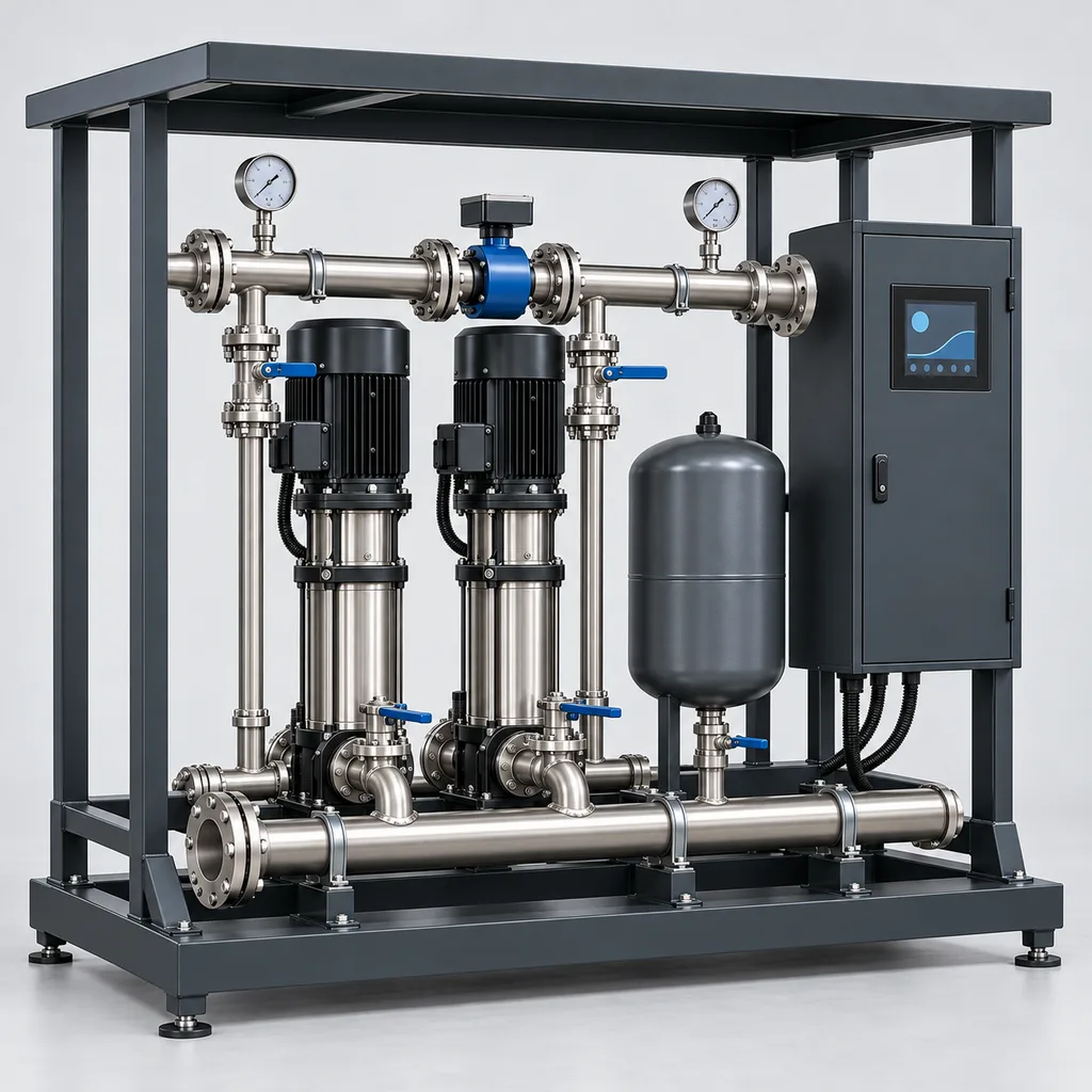
The RC-IBS-700 is a mains-powered smart irrigation booster pump station that combines a packaged hydraulic skid, local pressure control, a Web management platform and a mobile App. It serves parks, campuses, sports grounds and commercial landscapes where available water pressure varies or a storage tank must supply multiple irrigation zones. The reference package uses two independently controlled pumps to deliver a combined design duty of 30 m³/h at 50 m total differential head, with pump staging matched to changing demand. REDCOAST.LTD develops the station controller, sensor-interface PCB and application software in-house, while selecting serviceable pumps and variable-frequency drives against the approved hydraulic duty.
Key Features
- Defined hydraulic package: Two vertical multistage centrifugal pumps, each with a 4 kW motor, provide a reference station duty of 30 m³/h at 50 m differential head; final pump curves and skid losses form part of project selection.
- Pressure matched to irrigation demand: Local feedback adjusts pump speed as sprinkler or drip zones change, with a configurable 2–6 bar outlet-pressure setpoint inside the selected pump operating envelope.
- Automatic lead-pump rotation: Operating hours and availability determine which pump starts first, distributing running time and allowing maintenance of an isolated pump.
- Separate capacity and redundancy choices: The reference two-pump package provides approximately 15 m³/h at the reference head with one pump unavailable; an optional three-pump arrangement provides two-duty, one-standby operation.
- Custom board-level controls: REDCOAST.LTD designs pressure-signal conditioning, isolated field I/O, drive interfaces and watchdog circuitry around the project's sensors and operating sequence.
- Measured operating performance: Flow, pressure, energy, operating hours and alarm history appear together in the Web platform and App, supporting comparison of irrigation cycles.
- Protection at the station: Low-water, high-pressure, drive-fault and emergency-stop inputs act locally; pump protection does not depend on an internet connection.
- Integration with existing irrigation equipment: Pump-enable contacts and Modbus interfaces connect to landscape controllers, tank-level equipment and filtration systems without replacing every downstream valve controller.
Technical Architecture
The skid includes two parallel pump branches with individual isolation and check valves, a DN80 suction header, a DN65 discharge header, an electromagnetic flow meter and an outlet pressure transmitter. A 60 L diaphragm pressure vessel buffers small draw-offs and helps limit starts; its usable drawdown is considerably smaller than its nominal volume and depends on precharge and operating pressure. The standard arrangement takes clean irrigation water from a tank with flooded suction. A coarse strainer protects the pump inlet where required, while irrigation-grade filtration is selected separately for the water source and downstream emitters.
The REDCOAST.LTD controller reads pressure, flow and permissive signals through a custom signal-conditioning and I/O PCB. A local pressure loop commands each drive, adds the second pump after sustained demand and removes it with hysteresis when demand falls. The sequence includes low-flow sleep, controlled wake-up, operating-hour rotation and a pipe-fill mode that limits flow during initial charging. An independent high-pressure switch, low-level interlock and emergency-stop circuit interrupt pump permission through the specified electrical protection chain. Sensor failure or invalid control data produces a defined stop-and-alarm response rather than an unrestricted speed command.
The edge controller records one-minute summaries and timestamped events, then sends them to the Web platform when a connection is available. Operators can review pressure trends, pumped volume, electricity consumption and maintenance counters from the App. Remote commands are authenticated, logged and checked against local operating limits; local Off and protection inputs retain priority. The base station accepts irrigation demand from an external scheduler, while optional zone-status exchange improves coordination with master valves and filter backwash. Fertilizer dosing and water treatment remain separately engineered processes.
Connectivity & Power
The reference electrical build uses AC 400 V, three-phase, 50 Hz power with protective earth. Each 4 kW motor has its own drive, and an internal control-power supply provides 24 V DC for electronics and instruments. The combined 8 kW motor rating is mechanical output capacity, not the station's electricity consumption. At the reference hydraulic duty, preliminary electrical demand is approximately 6–8 kW, excluding optional enclosure climate equipment; the selected pump efficiencies, drive losses and factory measurements determine the final value. Separate 208–230 V, 60 Hz and 460 V, 60 Hz builds require matching motors, drives and protection equipment.
Ethernet is the preferred connection where a managed site network exists; an optional LTE Cat 1 or Cat 4 modem suits installations without nearby network cabling. RS-485 Modbus RTU connects local meters and drives, while Modbus TCP and MQTT over TLS support approved supervisory integration. Public-internet control requires the project network security configuration, and serial Modbus remains on the protected equipment network. Loss of communications leaves local pressure regulation active while mains power and water remain available. Loss of mains stops pumping; restart follows the configured permissive checks and restart delay.
Protection & Reliability
The control enclosure is specified to IP55, with sealed cable entries and a cooling arrangement selected for the actual heat load. This rating concerns the electrical enclosure; the complete skid is not submersible. The reference operating environment is +5 to +40 °C, with clean water between +5 and +40 °C. Colder installations require drainage or a separately sized insulated, heated enclosure, while hotter installations require drive derating and a documented cooling calculation. Cabinet heaters alone do not protect exposed water-filled pipes against freezing.
The steel skid, cabinet and weather canopy receive hot-dip galvanizing beneath a smooth matte powder-coated finish. Coastal sites require an agreed coating system, suitable fasteners and materials selected against the water chemistry; stainless steel does not automatically make a pump suitable for seawater. Canopy anchorage is designed for the site's wind loading, and the base must sit above the assessed flood level with adequate drainage. Motor temperature, dry-running conditions and cabinet temperature are monitored alongside maintenance counters. Seal life, vessel service intervals and warranty coverage are defined against operating hours, water quality and the agreed service plan rather than an unsupported universal lifespan.
Application Scenarios
- Municipal parks and landscaped avenues: A station beside an irrigation tank supplies sprinkler groups that open at different times. Pressure feedback reduces the need for operators to adjust fixed throttling valves whenever the active zone changes.
- Sports grounds and training facilities: Grounds teams can schedule several fields within a limited watering window while observing station capacity. Pump staging supports changing demand, and measured volume helps compare planned and actual watering cycles.
- University and business campuses: A central irrigation network may span lawns, planted courtyards and elevated landscape areas. The station provides a defined pressure source and exposes alarms to the facilities management platform.
- Commercial nurseries: Separate nursery blocks can request water through the existing irrigation controller. Low-flow demand is addressed through vessel drawdown or a selected jockey pump, avoiding continuous operation below the main pumps' permitted minimum flow.
- Landscapes using treated reclaimed water: A dedicated non-potable tank can supply irrigation after the required upstream treatment and filtration. The station monitors available water and pumping performance, while source separation and water-quality compliance remain part of the site design.
Case-style Examples
The following are illustrative configurations, not claims of completed installations or measured customer savings.
Public park pump-room replacement: A park has a storage tank and irrigation blocks whose combined scheduled demand reaches 28 m³/h at approximately 5 bar station outlet pressure. The two-pump RC-IBS-700 reference arrangement, Ethernet connection and existing controller's pump-enable contact form the proposed package, subject to suction and pipe-loss checks. Its intended result is automatic pressure regulation and a shared operating record, with a reduced irrigation schedule available during single-pump maintenance.
Sports-ground maintenance continuity: A facility needs approximately 30 m³/h during its overnight watering window and wants that capacity available while one pump is serviced. A three-pump configuration uses two duty pumps and one standby pump, with electrical equipment and pipework sized for the revised arrangement. This provides a defined N+1 selection basis at the specified duty instead of treating the standard two-pump package as full-capacity redundancy.
Nursery with small drip blocks: A nursery alternates high-flow sprinkler irrigation with drip blocks requiring about 1 m³/h. The project adds a small jockey pump selected for that low-flow duty and uses an LTE connection for remote maintenance access. The intended benefit is stable supply across two different demand ranges; the jockey pump and main-pump transitions are verified during commissioning.
Customization & Selection Guide
Start with simultaneous zone flow, the required pressure at the most demanding emitter, elevation differences and pipe, valve and filter losses. For example, an emitter needing 3.0 bar, a 10 m elevation rise and approximately 1.0 bar of distribution loss requires about 5.0 bar at the station outlet before any additional design allowance. The pump differential head must then account for the available inlet pressure. Check the minimum tank level, suction-line losses, liquid temperature and pump NPSH requirement before selecting the pump; flooded suction does not remove the need for this calculation.
The reference 30 m³/h at 50 m point represents simultaneous flow and head at the skid interfaces. It is not a promise that every flow is available at every pressure setting. Pump selection uses full hydraulic curves and minimum-flow limits, as illustrated by the performance data in Xylem's e-SV technical catalogue. A compact variable-speed package is an established commercial irrigation format, also documented in Rain Bird's 2025 landscape irrigation guide.
Choose two pumps where reduced output during maintenance is acceptable, or three pumps where the agreed peak duty needs one-pump redundancy. Specify a jockey pump when sustained low flow falls below the main pumps' operating limits. Select wetted materials from a water analysis, and add downstream filtration to the emitter manufacturer's requirements. Direct connection to a potable distribution main requires utility permission and a suitable backflow-protection design; the standard tank-fed arrangement avoids assuming that direct boosting is permitted everywhere. Energy savings must be assessed against the existing system and actual duty profile, without a fixed percentage promise.
Deployment & After-sales
Installation requires a level structural base, independent pipe supports, service clearance, a correctly protected electrical feeder, earthing and a drainage route. The site team verifies available water level, suction conditions and pressure ratings before filling and venting the pumps. Commissioning includes rotation checks, pressure-sensor verification, flow checks, lead/assist transitions, low-water and high-pressure trips, communications-loss behavior and restart after supply restoration. Ramp settings are coordinated with valve timing; a long pipeline may need a separate hydraulic-transient study and surge-protection equipment.
The delivery plan separates hydraulic selection, control-panel approval, any new PCB development, fabrication and factory acceptance testing. A new board revision adds prototype and environmental-verification work, so production lead time is confirmed against the agreed configuration and component availability. Deliverables can include general-arrangement drawings, electrical schematics, the agreed pump curves, I/O schedules, configuration backups, test records and operator training. After-sales scope covers remote diagnostics, firmware maintenance, replaceable controller assemblies and a project spare-parts list; warranty duration and service response commitments are stated in the quotation.
Standards & Compliance
Project specifications and acceptance evidence are agreed for the exact delivered configuration. The ratings and performance figures on this page define a reference engineering configuration and selection targets, rather than reporting completed certification or site testing.
- Hydraulic acceptance testing can be specified to ISO 9906:2012, with the test boundary and acceptance grade stated in the purchase specification.
- Machine electrical design references IEC 60204-1:2016 with Amendment 1:2021. Controlgear assemblies use IEC 61439-1 together with the applicable assembly-specific part, as required by the IEC 61439-1:2020 scope.
- Enclosure protection is verified using IEC 60529; installing cooling equipment, displays or cable glands must preserve the specified assembled-enclosure rating.
- Drive-system EMC assessment references IEC 61800-3:2022, including its 2025 corrigendum, with filters, cable arrangements and installation environment included.
- Potable-source interfaces require the locally applicable backflow assessment. Where specified, EN 1717:2025+A1:2026 provides a relevant assessment framework.
- CE documentation, RoHS evidence, radio approvals and pressure-vessel documentation are included where required by the destination and contracted scope. Component documentation does not by itself certify the complete station.
Why REDCOAST.LTD
REDCOAST.LTD delivers the pumping equipment, control electronics, Web platform and mobile App as one coordinated irrigation solution. In-house PCB development allows the team to change sensor interfaces, isolation, I/O allocation, drive communications and enclosure connections when a project needs more than a standard controller configuration. Hydraulic equipment is selected for the duty, while the proprietary board-level hardware and software provide the required control behavior and operational visibility. This combination supports both new sites and upgrades that must retain existing irrigation controllers, field valves or management systems.
Contact REDCOAST.LTD with your simultaneous irrigation flow, required pressure, water source, electrical supply and site layout to request a configured RC-IBS-700 proposal.
Specifications
Hydraulic Performance — Reference Configuration
- Pump Arrangement
- 2 parallel vertical multistage centrifugal pumps; independent variable-speed drives
- Combined Design Flow
- 30 at 50 m total differential head; selection target at skid interfaces m³/h
- Reference Differential Head
- 50 at 30 m³/h combined flow m
- Single-Pump Design Duty
- 15 at 50 m differential head; reduced capacity with one pump unavailable m³/h
- Outlet Pressure Setpoint
- 2–6; restricted to the selected pump curve and system limits bar(g)
- Pressure Limits
- PN16 manifolds; 10 bar maximum working pressure for the reference assembled hydraulic package
- Diaphragm Pressure Vessel
- 60 nominal volume; 10 bar maximum working pressure; drawdown depends on precharge L
Mains Power & Drives
- Reference Supply
- AC 400 ±10%; three-phase with protective earth V
- Reference Supply Frequency
- 50 Hz
- Installed Motor Output
- 2 × 4; 8 total mechanical rated output kW
- Drive Rating
- 2 × 5.5; final output-current and temperature rating matched to motors kW
- Estimated Input at Reference Duty
- 6–8; preliminary, both pumps combined, excluding optional enclosure climate equipment kW
- Controls & Telemetry Consumption
- 25–60; pumps and enclosure climate equipment excluded W
- Internal Control Supply
- 24 DC; 5 A rated output V
Instrumentation & Measurement
- Pressure Transmitters
- 2 × 0–10; suction and discharge bar(g)
- Pressure Transmitter Accuracy
- ±0.5% of full scale at 20–25 °C; selected-sensor specification
- Electromagnetic Flow Meter
- DN65; reference calibrated service range 6–30 m³/h
- Flow Measurement Accuracy Target
- ±0.5% of reading at 0.5–5 m/s; full pipe and specified straight runs
- Minimum Water Conductivity
- 20 for the reference electromagnetic meter µS/cm
- Tank Low-Level Interlock
- 1 independent float-switch input; additional level transmitter via 4–20 mA or RS-485
- Electrical Measurements
- Three-phase voltage, current, active power, energy and power factor; RS-485 meter
Local Control & Custom PCB Interfaces
- Analogue Inputs
- 6 × 4–20 mA; 16-bit conversion
- Analogue Outputs
- 2 × 4–20 mA
- Digital Inputs
- 12 × 24 V DC optically isolated
- Relay Outputs
- 8 dry contacts; 2 A at 24 V DC resistive load; control circuits only
- Pressure-Control Update Period
- 100 target; independent of cloud reporting ms
- Drive Command Band
- 30–50 for the 50 Hz build; pump-specific minimum flow and speed enforced Hz
- Acceleration & Deceleration Setting
- 5–60; commissioned to pipework and valve sequence s
- Steady-State Pressure Regulation Target
- ±0.2 at the commissioned duty; excludes valve-switching transients and sleep cycles bar
Connectivity, Platform & Data
- Ethernet
- 1 × RJ45, 10/100 Mbit/s
- Serial Field Interfaces
- 2 isolated RS-485 ports
- Optional Cellular Modem
- LTE Cat 1 or LTE Cat 4; bands and carrier approval selected per deployment
- Integration Protocols
- Modbus RTU, Modbus TCP and MQTT over TLS 1.2 or later
- Local Data Buffer
- 30 days of one-minute records for 32 channels, plus timestamped events
- Telemetry Reporting Interval
- 60–900 configurable; alarm messages queued immediately s
- Local HMI
- 7-inch touchscreen; 800 × 480 display
- Software Delivery
- Web dashboard and mobile App; hosted service or customer-managed server
Protection & Operating Environment
- Control Enclosure Protection
- IP55 design target for the assembled cabinet
- Motor Enclosure Protection
- IP55 minimum specified
- Reference Ambient Temperature
- +5 to +40; extended climates require a separate thermal package °C
- Reference Water Temperature
- +5 to +40; non-freezing service °C
- Ambient Humidity
- 10–95, non-condensing % RH
- Reference Installation Altitude
- 0–1,000; higher elevations require pump and drive review m
- Local Protection Inputs
- Low water, independent high pressure, motor/drive fault and emergency stop
- Power-Restoration Delay
- 30–300; restart only with valid permissives and enabled automatic mode s
Mechanical Construction & Installation
- Suction Connection
- DN80 flanged header
- Discharge Connection
- DN65 flanged header
- Reference Overall Envelope
- 1,800 × 1,000 × 1,700; length × width × height; finalized on approved drawing mm
- Reference Manifold Material
- 304 stainless steel; 316 option after water-chemistry review
- Skid, Cabinet & Canopy Finish
- Hot-dip galvanized steel with smooth matte powder coating, RAL 7016 anthracite
- Recommended Service Clearance
- 800 at control-panel front; 600 at service sides, subject to local requirements mm
- Standard Water-Source Arrangement
- Tank-fed flooded suction; independently supported pipework and drained structural base
Capabilities — configurable per project
Specifications are tailored to each project — the options below show what we can support.
Duty & Maintenance Continuity
- Two pumps, lead/assist: 30 m³/h at 50 m reference duty
- Two pumps, duty/standby: 15 m³/h at 50 m reference duty
- Three pumps, two duty plus one standby: 30 m³/h at 50 m reference duty
Electrical Build
- 400 V three-phase, 50 Hz reference build
- 208–230 V three-phase, 60 Hz matched motor/drive build
- 460 V three-phase, 60 Hz matched motor/drive build
Hydraulic Additions
- 0.75–1.5 kW jockey pump for sustained low-flow demand
- 100–130 µm downstream disc filtration selected for emitters
- Remote pressure transmitter at the critical irrigation zone
Climate Package
- Standard +5 to +40 °C installation with weather canopy
- Insulated housing and calculated pipe heat tracing for freezing sites
- Closed-loop cabinet cooling and drive derating for hot sites
System Integration
- Ethernet with existing irrigation-controller pump-enable contact
- LTE Cat 1 or Cat 4 with hosted Web platform and App
- Modbus TCP integration with customer-managed platform
Related solution guidance
Environmental Monitoring
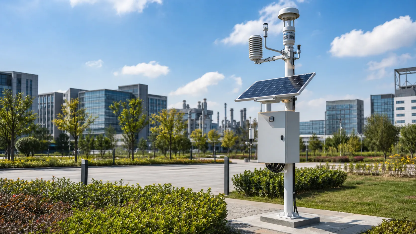
Deploy environmental monitoring stations with sensors, solar power, gateways, dashboards, alarms and data integration for city and industrial sites.
Ports and Logistics
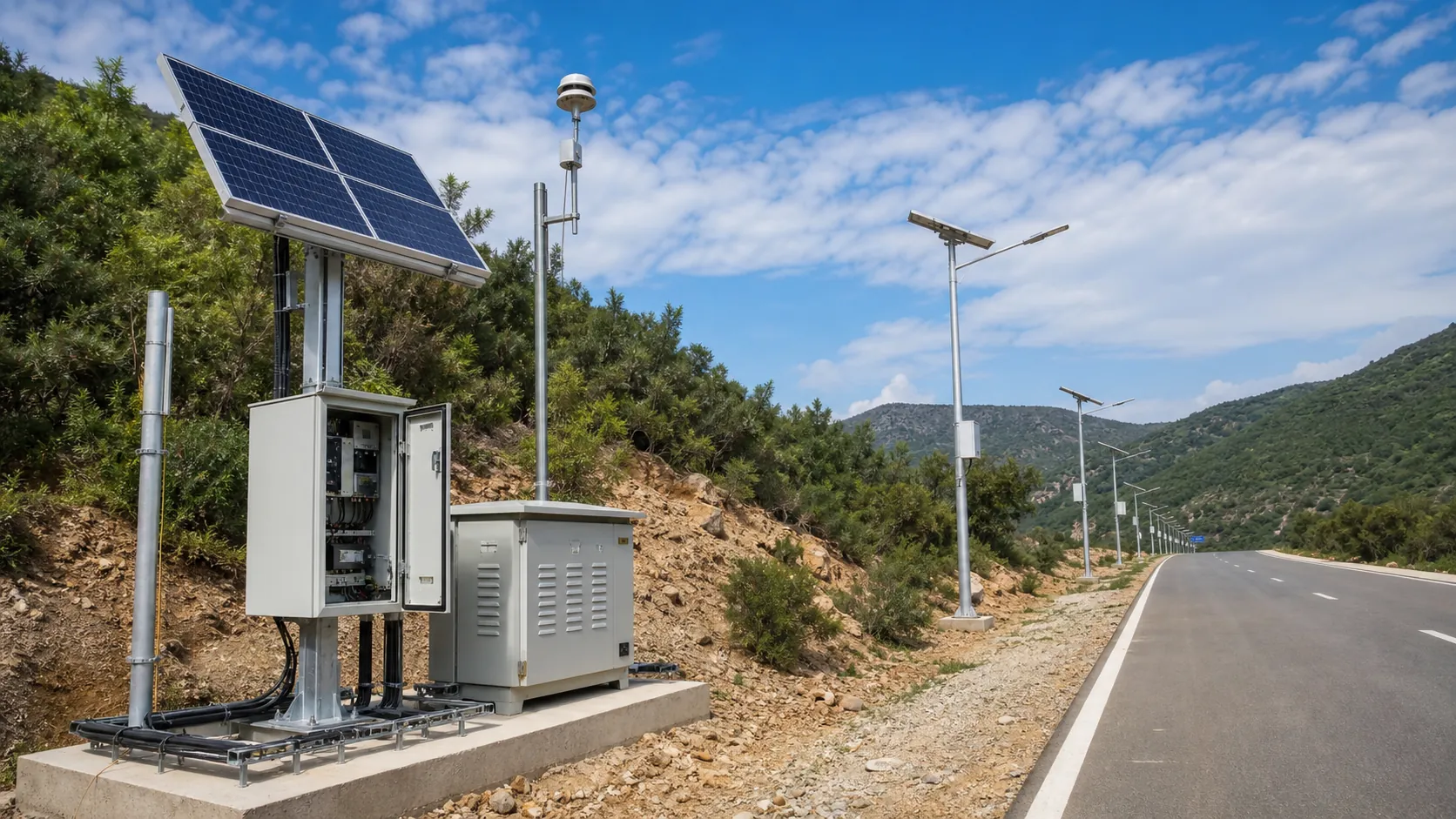
Outdoor IoT infrastructure for ports, yards and logistics areas: lighting, guidance, safety, solar power, monitoring and maintenance visibility.
Power and Connectivity
How to choose power, battery, solar, NB-IoT, LTE, LoRaWAN, gateways and monitoring strategy for outdoor IoT infrastructure.
Frequently Asked Questions
How is an irrigation booster pump station different from an irrigation controller?
An irrigation controller schedules field valves, while a booster pump station supplies the hydraulic flow and pressure those valves need. The RC-IBS-700 combines pumps, local pressure control, measurement and remote supervision, and can accept a pump-enable signal from an existing irrigation controller. REDCOAST.LTD develops its control PCB and software to match the project's interfaces.
How do I size the RC-IBS-700 for a park or sports ground?
Specify the flow of zones that operate simultaneously, required emitter pressure, elevation changes, distribution losses and minimum available inlet pressure. The reference selection target is 30 m³/h at 50 m total differential head across the skid; this is a paired operating point. Land area alone is insufficient because watering depth, irrigation window and emitter selection change the required duty.
Does the standard two-pump station provide full-capacity backup?
No. Both reference pumps are needed for the 30 m³/h design duty, and one remaining pump is selected for approximately 15 m³/h at the same reference head. Select a three-pump, two-duty/one-standby configuration if 30 m³/h must remain available with one pump out of service.
Can the pump station connect directly to the municipal water main?
The standard configuration takes water from a tank with flooded suction. Direct boosting requires confirmation of utility permission, minimum inlet conditions and the applicable backflow-protection arrangement. An irrigation network or reclaimed-water connection must not rely on a software interlock or ordinary pump check valve as its sole potable-water protection.
What happens if the internet or mains power fails?
With mains power and water available, loss of internet does not stop local pressure control; records are buffered for later upload. Mains failure stops the pumps because the reference package has no backup pumping supply. After restoration, automatic restart requires valid local permissives, an enabled automatic mode and the configured restart delay.
Can it pump reclaimed water or water containing sand?
Treated reclaimed water may be suitable after checking solids, chemistry, seal materials and site water-use requirements. The reference multistage pumps require clean water, so an intake strainer alone does not make sandy or abrasive water acceptable. Upstream treatment and downstream emitter filtration are selected separately, and the station itself does not disinfect water.
How much electricity will the irrigation pump station use?
At 30 m³/h and 50 m differential head, the hydraulic power delivered to the water is approximately 4.09 kW. A preliminary combined electrical input of 6–8 kW is physically plausible after pump, motor and drive losses, but the selected equipment and acceptance test establish actual consumption. The two 4 kW motor ratings describe installed mechanical output capacity, and no fixed energy-saving percentage is promised.
What information is needed for a customized quotation?
Provide the simultaneous flow, required outlet pressure, water analysis, source-tank levels, pipe layout, electrical supply and ambient conditions. Include the existing irrigation controller and platform interface requirements so REDCOAST.LTD can define the custom PCB, firmware and integration scope. The quotation should identify the hydraulic guarantee point, redundancy requirement, acceptance tests, delivery schedule, warranty and spare-parts package.