Overview
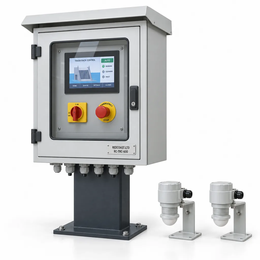
The RC-TRC-600 is a mains-powered automatic trash rack cleaning control and intake blockage monitoring station for irrigation operators, water utilities, industrial facilities and infrastructure integrators. It measures water levels upstream and downstream of a screen, starts a compatible mechanical rake when cleaning is needed, and reports unresolved blockage or equipment faults through a Web platform and mobile app. The standard package combines two radar level sensors, an outdoor control cabinet, a motor starter, local controls and connected maintenance records. REDCOAST.LTD delivers the complete monitoring and control solution, supported by in-house PCB and board-level hardware development for project-specific interfaces.
Key Features
- Demand-based cleaning: Differential water level initiates a cleaning request, with adjustable persistence and hysteresis to avoid unnecessary starts during waves or changing flow.
- Two independent level measurements: Upstream and downstream radar readings distinguish screen head loss from changes in the overall channel level.
- One complete control package: A 7-inch HMI, motor starter, field terminals, alarm beacon interface and Web/mobile access cover installation, operation and maintenance.
- Mechanical fault supervision: Motor overload, missing movement feedback and excessive cycle duration produce separate alarms with recorded operating conditions.
- Local operation without internet: Cleaning sequences and equipment interlocks execute inside the cabinet; cloud connectivity provides oversight and records.
- Purpose-built electronics: REDCOAST.LTD develops the isolated sensor interface, digital I/O, edge controller and DC power supervision PCBs to match the installation.
- Existing equipment integration: Discrete start/stop, run feedback and fault contacts allow connection to a surveyed rake or an existing motor control center.
- Actionable maintenance history: Cleaning counts, motor running hours, head-loss trends and unresolved alarms help crews prioritize inspection and debris collection.
Technical Architecture
Two downward-looking 80 GHz radar sensors mount on opposite sides of the trash rack, clear of the rake travel and strong hydraulic disturbances. Their surveyed mounting elevations establish a common water-level datum; subtracting raw distances without these offsets would give an incorrect differential. The controller receives isolated 4–20 mA signals, applies configurable damping and checks signal validity before calculating head loss. Non-contact radar is an established option for water level and open-channel applications, as illustrated by VEGA's current radar sensor specifications. RC-TRC-600 sensor range and accuracy are specified for the selected project instruments; turbulence, mounting geometry and calibration remain part of installed-system acceptance.
The edge controller combines differential level, a backup schedule, upstream high-level status and machine permissives. An illustrative commissioning setting requests cleaning after a 100 mm differential persists for 10 seconds and clears that request below 40 mm; these are starting values, not universal limits. The sequence checks guards and motor availability, gives a local pre-start warning, runs the rake and verifies movement. It completes the current mechanical cycle before a normal stop when the machine requires a home position. Persistent head loss after the permitted cycles raises an unsuccessful-cleaning alarm; overload, safety trips or loss of motion stop the machine and latch a fault. Automatic jam reversal is disabled in the base configuration. Invalid level inputs suspend differential control and raise an alarm; timer-only fallback requires approval in the site's hydraulic and machinery risk assessment.
A separate safety relay and appropriately selected contactors handle emergency-stop and guard circuits independently of the IoT processor. The custom boards manage process control, isolated acquisition, event logging and communications, while approved industrial components switch mains motor power. An optional bin-full sensor prevents repeated discharge into an overflowing container. The platform associates each event with an asset, timestamp, water levels and machine state; operators can acknowledge maintenance alarms, assign inspections and export records. Remote start requires a locally enabled remote mode and all permissives. Safety resets require local action.
Connectivity & Power
This product is intended for permanent sites with an electrical service: pumping compounds, canal headworks, treatment facilities and managed industrial or campus drainage systems. The direct-motor configuration uses a factory-selected three-phase AC 380–415 V, 50 Hz supply or AC 440–480 V, 60 Hz supply, matched to the motor and protective devices. A separate interface-only configuration uses AC 100–240 V, 50/60 Hz and sends commands to an existing motor control center. These are distinct wiring configurations; the universal control supply does not make a motor compatible with every grid.
Ethernet is the standard connection for a plant network. Optional 4G LTE provides backhaul where a wired network is unavailable, with modem bands selected for the destination and carrier. Modbus RTU or Modbus TCP exchanges process values with site SCADA, while MQTT over TLS or HTTPS connects the Web platform and mobile service. Unencrypted industrial protocols remain inside a controlled network or VPN. Cellular subscriptions and remote hosting are scoped separately.
The electronics and two sensors have a planning consumption of 25–40 W, excluding the motor and optional mains-fed 100 W enclosure heater. Motor nameplate output is mechanical shaft power, so electrical consumption must include motor losses and actual running time. For illustration, a measured 0.95 kW motor input running for 30 minutes daily plus 30 W of continuous controls would consume approximately 1.20 kWh per day, before heating. The station uses mains power throughout; loss of supply stops the rake, and restart behavior is commissioned for the specific machine.
Protection & Reliability
The outdoor cabinet has an IP66 design target for the completed assembly, including its door, controls and cable glands. Its steel enclosure and mounting hardware use hot-dip galvanizing beneath a smooth matte powder-coated finish; the standard colors are RAL 7035 light grey for the cabinet and RAL 7016 anthracite for the pedestal and brackets. A sun shield limits direct solar heating. The specified operating envelope is -20 to +50 °C with the cold-weather heater fitted, subject to the selected HMI, starter and sensor ratings.
Replaceable surge protection, protective bonding, separated mains and signal wiring, conformal-coated control boards and a humidity-controlled heater address common outdoor failure mechanisms. Coastal installations require a coating and fastener specification based on actual chloride exposure; no universal salt-spray lifetime is implied. Wind anchorage is checked against local loads and the selected pedestal. Cabinet cold-weather operation does not establish that a rake can break ice or operate in a frozen channel.
Motor running hours and contactor operations support planned replacement, while removable terminal blocks simplify board servicing. Maintenance includes checking sensor alignment, glands, door seals, protective devices and the rake manufacturer's lubrication and wear points. Warranty scope, spare-parts arrangements and service response are documented in the project quotation.
Application Scenarios
- Irrigation pumping intakes: Install beside an electrically powered canal pump station where weeds and floating refuse accumulate on the inlet rack. Cleaning responds to measured head loss, while crews receive fault and debris-bin notifications before the next inspection round.
- Canal-to-pipeline headworks: Monitor the rack ahead of an enclosed conveyance pipeline at a grid-connected control compound. Head-loss and cleaning records help operators distinguish screen obstruction from downstream operating changes.
- Municipal raw-water abstraction: Connect to a treatment plant's existing coarse-screen rake and SCADA network. Operators can coordinate inspection with rising upstream levels and retain a traceable history of cleaning attempts.
- Industrial utility-water intakes: Use the station at a factory's non-potable cooling or process-water intake. Motor fault feedback and persistent-blockage alarms support a site-specific response before restricted intake flow affects production.
- Campus and park drainage inlets: Fit a guarded mechanical screen at a maintained stormwater collection point with an existing electrical service. Remote status helps maintenance teams prioritize debris removal during leaf fall and rainfall events, while hydraulic overflow provisions remain part of the civil design.
Case-style Examples
The following examples illustrate configurations and intended operating outcomes; they are not claims of completed customer installations.
Irrigation intake modernization: An operator has a 0.75 kW powered rake but relies on fixed cleaning intervals and visits to identify blockage. A two-radar RC-TRC-600 package adds differential-level control, movement feedback and LTE reporting while retaining the surveyed mechanism. The expected result is a visible record of whether each cleaning cycle restores the intake condition, enabling maintenance to respond to unresolved obstructions.
Treatment-plant screen retrofit: A plant already operates a starter panel and Ethernet SCADA but lacks reliable head-loss information. The interface-only version supplies AC 100–240 V controls, two level sensors and isolated start, availability and fault signals to the existing panel. The intended outcome is automatic cleaning coordination and centralized alarm history without duplicating the installed motor starter.
Seasonal leaf-loading at a drainage intake: A managed campus has a 1.5 kW screen rake and a collection bin that fills rapidly in autumn. The selected configuration adds bin-full sensing, a local warning beacon and alarm escalation to maintenance staff. When the bin is full, the controller inhibits further discharge and reports the condition; a separately engineered overflow path accommodates continued inflow.
Customization & Selection Guide
Begin with the screen and machine survey: channel dimensions, minimum and maximum water levels, allowable differential head, debris type, rake geometry, motor voltage, motor current and the existing safety circuit. Automatic raking and differential-level control are established arrangements for irrigation canals, water intakes and drainage facilities; Duperon's manufacturer data provides a relevant industry example. Compatibility with a particular installed machine still requires its drawings and interface review.
Choose the direct-motor cabinet for a compatible single rake with a 0.37–2.2 kW three-phase motor. Choose the interface-only version where an existing starter or larger drive already controls the machine. Select Ethernet for an available plant network, LTE for isolated communications, and an additional bin sensor where collection capacity limits operation. A VFD interface is an engineering option when approved by the machine supplier; minimum speed, torque and motor cooling must be checked.
Screen spacing, channel flow capacity and maximum allowable head loss belong to the hydraulic and mechanical design. The RC-TRC-600 does not assign a universal flow rating to an existing rack, and coarse debris screening does not establish fish protection or fine filtration performance. Buyers needing aquatic-life protection should specify a dedicated intake-screen design; official fish-screening guidance explains why a conventional trash rack is insufficient.
Deployment & After-sales
The standard supply consists of the configured cabinet, two radar sensors with mounting brackets, controller firmware, HMI screens, wiring documentation and the agreed Web/mobile software package. Mechanical rakes, racks, conveyors, bins, civil works and hydraulic bypasses are separately scoped. REDCOAST.LTD can coordinate an integrated package after the mechanical interfaces and supply responsibilities are agreed.
Installation starts with a site survey and I/O schedule, followed by cabinet drawings, sensor locations and an approved control sequence. Factory acceptance covers signal simulation, motor-control interfaces, interlocks, alarm delivery and network-loss behavior. Site acceptance establishes the common level datum, checks real rake travel and stopping, and demonstrates the cleaning response under available flow conditions. A forced blockage is not required where it would exceed the rack's allowable loading.
Delivery timing is quoted after component availability, PCB customization and mechanical interfaces are frozen; a repeat cabinet configuration has a different schedule from a new board design. Handover includes configuration backups, terminal schedules, a spare-parts list, operator training and an agreed support route. Remote diagnostics require authorized access, and firmware updates follow controlled maintenance procedures.
Standards & Compliance
The project compliance plan uses IEC 60204-1, including its 2021 amendment, for the machine electrical equipment, protective bonding, supply isolation and related documentation. Machinery risk assessment follows ISO 12100. Safety functions and their required performance levels are determined for the complete installation; ISO 13849-1:2023 provides the relevant control-system design methodology, rather than automatically assigning a safety rating to the IoT controller.
Enclosure ingress testing is specified against IEC 60529. The project also establishes applicable EMC, electrical assembly, radio, material-restriction and destination-market conformity requirements. IP66, operating-temperature limits and any conformity marking must be supported by the final configuration's evidence. The values on this page define an engineering configuration and procurement targets, not a claim that a newly customized assembly already holds third-party certification.
Why REDCOAST.LTD
REDCOAST.LTD combines outdoor hardware, embedded control, a Web management platform and mobile workflows in one project delivery. Its in-house engineering team can develop new PCBs for the required sensor conditioning, galvanic isolation, machine I/O, communications and DC power supervision, then adapt firmware and software to the operating process. This gives owners a practical route to standardize monitoring across different intake machines while retaining suitable installed mechanical equipment. Documented interfaces and maintainable board assemblies help integrators manage commissioning, future expansion and service.
Contact REDCOAST.LTD with your intake drawings, rake motor details, available mains supply and monitoring requirements to request a customized RC-TRC-600 proposal.
Specifications
Level Measurement
- Radar sensors included
- 2; upstream and downstream
- Radar operating frequency
- 80 GHz
- Configured measurement distance
- 0.3–8.0; clear line of sight m
- Selected sensor accuracy requirement
- ±5 or better under manufacturer reference conditions; installed differential verified on site mm
- Sensor output
- 4–20; two-wire loop mA
- Level acquisition interval
- 1 s
- Process signal damping
- 1–30; adjustable s
Cleaning Sequence & Supervision
- Controlled rake mechanisms
- 1 per cabinet
- Differential start threshold
- 30–300; limited by approved rack loading mm
- Start-condition persistence
- 2–60 s
- Differential hysteresis
- 10–100; below the selected start threshold mm
- Maximum cycle duration
- 30–600; matched to rake travel s
- Scheduled backup interval
- 15–1440; disabled until commissioned min
- Independent process alarm inputs
- 1 upstream high-high level; 1 bin-full input
- Safety and fault reset
- Local manual reset; 0 automatic jam-reversal attempts in base configuration
Custom Controller & Local Interface
- Analog acquisition
- 4 isolated 4–20 mA channels; 16-bit conversion
- Digital inputs
- 16 optically isolated channels; 24 V DC
- Digital outputs
- 8 protected 24 V DC outputs; 0.25 A per channel; interposing relays for external loads
- Serial interfaces
- 2 isolated RS-485 ports
- Local HMI
- 7-inch color touchscreen behind protective access door
- Local operating modes
- Off / Local / Remote-enabled automatic
- Safety circuit interface
- Dual-channel emergency-stop and guard inputs through a separate safety relay; installation validation required
Mains Power & Motor Interface
- Direct-motor supply, 50 Hz version
- Three-phase AC 380–415; 3P+PE V
- Direct-motor supply, 60 Hz version
- Three-phase AC 440–480; 3P+PE V
- Interface-only supply
- Single-phase AC 100–240, 50/60 Hz; external motor control center required V
- Compatible motor shaft rating
- 0.37–2.2; one three-phase motor, factory-matched starter and overload protection kW
- Internal control supply
- 24 V DC / 5 A; 120 W rated output
- Controls and sensor consumption
- 25–40 typical; excludes motor and heater W
- Anti-condensation heater option
- 100; separate mains-fed branch with thermostatic and humidity control W
- Mains switching arrangement
- Lockable isolator, branch protection, contactor and motor overload; motor current does not pass through the IoT PCB
Connectivity & Data
- Ethernet
- 1 × 10/100BASE-T port
- Cellular option
- 4G LTE Cat 1 or Cat 4; destination-specific bands
- Site integration protocols
- Modbus RTU / Modbus TCP
- Platform connection
- MQTT over TLS 1.2 or later / HTTPS
- Trend recording
- 32 selected tags at 60-second intervals
- Local history retention
- 30 minimum at the stated trend configuration; event records stored separately days
- Routine upload interval
- 10–3600; alarms queued immediately when connected s
- Storage
- 8; industrial nonvolatile storage with buffered replay after connection recovery GB
Enclosure & Environment
- Completed cabinet ingress target
- IP66; validation includes glands and external controls
- Cabinet dimensions, H × W × D
- 800 × 600 × 300; excludes pedestal and sun shield mm
- Operating ambient target
- -20 to +50; heater fitted for cold conditions, sun-shielded installation °C
- Internal operating humidity
- 5–95; non-condensing % RH
- Standard installation altitude
- 0–2000; higher elevations require electrical and thermal review m
- Cabinet finish
- Hot-dip galvanized steel with smooth matte powder coat; RAL 7035 cabinet / RAL 7016 pedestal
- Sensor protection requirement
- IP66 minimum; sealed outdoor cable termination
Capabilities — configurable per project
Specifications are tailored to each project — the options below show what we can support.
Electrical Integration
- 380–415 V three-phase direct-motor cabinet
- 440–480 V three-phase direct-motor cabinet
- 100–240 V interface-only cabinet for an existing motor control center
Communications & Platform
- Ethernet with site SCADA
- 4G LTE with hosted Web platform and mobile app
- Ethernet with customer-hosted server
Additional Monitoring
- Bin-full ultrasonic sensor
- Independent upstream high-high level switch
- Rake movement or home-position feedback kit
- External motor energy meter
Environmental Package
- Sun-shielded standard outdoor cabinet
- 100 W heater and humidity-control package
- Coastal fluorocarbon topcoat and upgraded fasteners
Machine Interface
- Direct-on-line single-rake starter
- Isolated start/stop and feedback to existing panel
- VFD command interface after motor and mechanism review
Related solution guidance
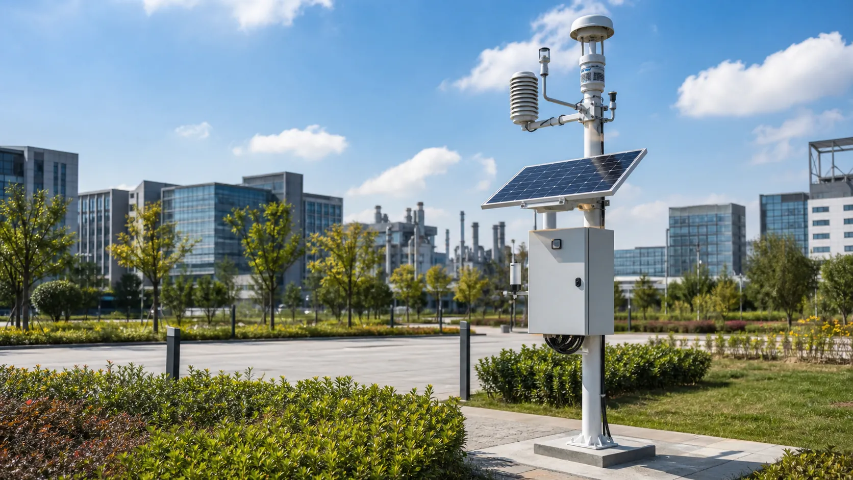
Environmental Monitoring
Deploy environmental monitoring stations with sensors, solar power, gateways, dashboards, alarms and data integration for city and industrial sites.
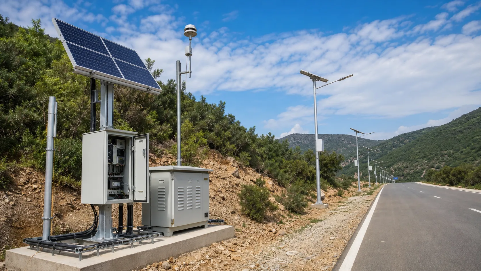
Solar IoT Guide
A design guide for solar-powered outdoor IoT: load calculation, battery autonomy, low-power firmware, telemetry and maintenance planning.
Solar Off-Grid IoT
Design solar-powered outdoor IoT systems with panels, batteries, controllers, low-power devices, gateways and remote power monitoring.
Frequently Asked Questions
What does an automatic trash rack cleaning controller do?
It monitors the water-level difference across a screen and requests cleaning when a configured condition persists. The RC-TRC-600 also checks machine availability, movement feedback and faults, then records whether head loss falls after cleaning. The compatible mechanical rake physically removes the debris.
Can the RC-TRC-600 retrofit an existing screen rake?
Yes, after checking the motor, controls, stopping behavior, guards and available feedback signals. The direct-motor version is specified for one compatible 0.37–2.2 kW three-phase motor; the interface-only version commands an existing motor control center. A manually cleaned rack needs a suitable mechanical cleaning mechanism before the station can automate debris removal.
Why are two water-level sensors required?
A single upstream level can rise because of higher inflow or downstream conditions, even when a rack is clear. Two measurements referenced to a common surveyed datum allow the controller to calculate differential level across the screen. Sensor placement, damping and field calibration are necessary to distinguish blockage from turbulence and normal hydraulic changes.
Does this station need solar panels or a battery?
The specified RC-TRC-600 is mains powered for sites with an existing electrical service. Its direct-motor cabinet is built for either the stated 50 Hz or 60 Hz three-phase supply, while the interface-only cabinet accepts AC 100–240 V. Backup power, if required, must be separately sized for the agreed controls and motor loads; it is not included in the base package.
What happens if the internet connection fails or the rake jams?
With mains power available, local control continues during an internet outage and records are retained for later upload. Overload, lost movement feedback or a safety trip stops the rake and latches a fault; the base configuration does not automatically reverse a jammed mechanism. A safety trip requires local reset, and invalid level signals suspend differential-based control.
Does a controlled trash rack provide fine filtration or fish protection?
The controller manages the installed coarse-screen mechanism and does not change its opening size or hydraulic characteristics. Fine filtration requires an appropriate downstream filter, and fish protection requires a dedicated intake design with the relevant openings, velocities and approvals. Flow capacity and allowable differential head must be established for the actual rack and channel.
Can REDCOAST.LTD customize the hardware and connect it to our SCADA?
REDCOAST.LTD can develop project-specific PCBs for isolated sensor acquisition, digital I/O, edge control and DC power supervision, together with firmware, Web software and mobile workflows. Standard integration uses Modbus RTU or Modbus TCP on a controlled network, with MQTT over TLS or HTTPS for platform access. Provide the I/O list, motor data, communications requirements and acceptance criteria so the hardware and software scope can be defined.