Overview
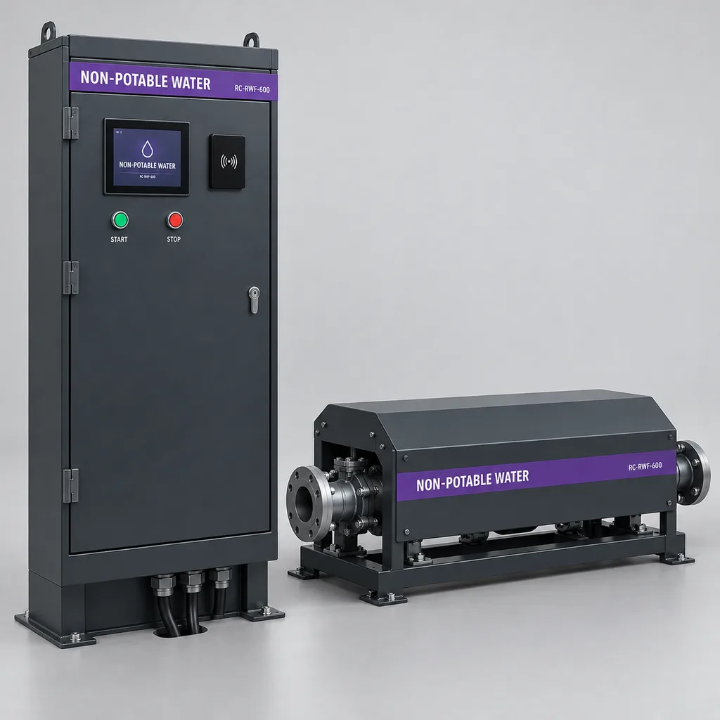
The RC-RWF-600 is a mains-powered reclaimed water tanker filling station from REDCOAST.LTD for water utilities, municipal service depots, industrial estates, and landscape maintenance fleets. It combines controlled driver access, measured bulk dispensing, local hydraulic interlocks, and an integrated Web platform and mobile app in one configurable solution. The reference package serves one loading bay through a DN80 metering assembly at a design flow of 10–40 m³/h, replacing shared keys and handwritten collection records with identifiable transactions. REDCOAST.LTD develops the station controller, valve-driver electronics, sensor interfaces, and application software, including new PCB layouts when project requirements demand them. Published values describe a proposed reference configuration for project engineering; final equipment ratings, verified performance, and acceptance criteria are established in the approved supply specification.
Key Features
- Accountable water collection: Associate each dispensing session with an authenticated driver credential, vehicle reference, project code, start time, delivered volume, and termination reason.
- Practical tanker throughput: Size the DN80 reference assembly for 10–40 m³/h, with a project-set flow limit that respects available supply pressure and upstream network capacity.
- Preset-volume dispensing: Let an authorized driver request a batch within the account allowance and confirmed tank capacity; compensate normal valve closure using commissioning measurements.
- Controlled access: Use 13.56 MHz cryptographic smart cards with application-level authentication, configurable access windows, and centrally managed credential revocation.
- Local process control: Evaluate inlet pressure, meter health, valve feedback, stop circuits, and supply-quality permission before opening the water path.
- Transparent accounting: Record actual measured delivery separately from requested volume, with exception handling for interrupted batches and exports for allocation or invoicing.
- Integrated operations software: Provide station maps, transaction searches, usage summaries, alarm acknowledgment, maintenance records, and mobile notifications through one platform.
- Project-specific hardware: Adapt isolated I/O, solenoid-drive protection, enclosure interfaces, and communication hardware through REDCOAST.LTD board-level engineering.
Technical Architecture
The reference system consists of a freestanding control kiosk, a separate covered hydraulic skid, and a fixed overhead loading arm. The skid includes manual isolation, a serviceable strainer, an electromagnetic flowmeter, pressure sensing, and a hydraulically operated dispensing valve with a flow-limiting pilot, configured to close when electrical permission is removed within its specified hydraulic operating conditions. The meter sits in a continuously flooded section, upstream of the control valve, with grounding and straight-run arrangements specified by its manufacturer. The loading arm discharges above an approved receiving opening with a maintained air gap; its support, vehicle clearance, drainage, and impact protection are engineered with the site layout.
Inside the kiosk, a REDCOAST.LTD controller PCB provides isolated pulse acquisition, 4–20 mA inputs, RS-485 interfaces, protected 24 V outputs, a watchdog, and nonvolatile transaction storage. Separate circuits handle the card reader, HMI, communications, and monitored valve supply. The meter remains a separately calibrated instrument: the custom PCB acquires its outputs and diagnostics without implying that a newly developed controller is itself a certified revenue meter. A reference instrument error specification of ±0.5% of reading plus a velocity term of ±1 mm/s is commercially established, but installation effects and batch stopping behavior require separate assessment. Endress+Hauser Promag W 400 technical information, revision 01.12.
The operating sequence is identify, authorize, confirm capacity, check permissives, open, measure, close, verify, and finalize. A hardwired stop circuit removes valve-opening permission independently of the cloud connection; it is a process stop and carries no claimed SIL or performance-level rating. Adjustable hydraulic closure reduces abrupt flow changes, while valve-position feedback and measured residual flow identify incomplete shutoff. The reference closing adjustment is 5–30 seconds, with the actual setting determined by pressure and surge testing. Any continuing flow after closure generates a lockout and an operator instruction to isolate the supply manually. Mains failure initiates closure, but discharge can continue during the closing interval; the interrupted transaction is held for review because delivery after loss of meter power cannot be assumed to have been measured. Restoration of power does not restart filling automatically.
Connectivity & Power
The station uses AC 100–240 V, 50/60 Hz from the depot or treatment-site electrical supply. An isolated 24 V DC supply powers field electronics and the valve pilot. The reference electrical budget is 20–30 W in standby, 35–60 W during dispensing, and 100 W maximum without heating; a 100–200 W cabinet heater raises the maximum connected station load to 300 W. Upstream pumps, external pipe heat tracing, lighting, and civil infrastructure have separate power budgets. Grid availability makes this configuration suitable for permanent urban and industrial loading points without photovoltaic equipment.
Ethernet is the preferred connection where a managed site network exists, with LTE Cat 1 as the alternative or backup. The integration package uses Modbus for local equipment and MQTT over TLS or HTTPS for platform communication. The controller executes batch control locally, so network latency does not determine valve stopping. During a communications outage, new prepaid transactions stop by default; an optional offline policy permits only previously reserved, station-specific volume allowances with an expiry time. These allowances cannot be spent again at another station while disconnected, and restored connectivity triggers transaction reconciliation before further credit is released.
Protection & Reliability
The electrical compartment has an IP66 design target, sealed cable entries, a protective earth connection, and separated mains and low-voltage wiring. The hydraulic hood is intentionally drained and ventilated; its protection must not be confused with the electrical compartment rating. Exterior carbon-steel cabinets, skid supports, and loading-arm supports receive hot-dip galvanizing followed by a smooth matte powder-coated finish, with a fluorocarbon topcoat option for more demanding exposure. Coating selection follows the assessed atmospheric environment, rather than treating a color or a short salt-spray test as proof of service life. ISO 12944-2:2017 environmental classification.
The unheated reference package is specified for ambient temperatures of +5 to +50 °C and water temperatures of +5 to +40 °C. Subzero service requires a project-specific thermal design covering the meter, valve pilot tubing, exposed pipes, and loading arm; heating the control kiosk alone does not protect the water path. Sand exposure calls for protected seals and accessible strainers, coastal exposure calls for appropriate fasteners and coating maintenance, and the overhead structure requires a site wind-load and foundation assessment. Replaceable controller modules, accessible terminals, and serviceable valve internals support maintainability; warranty terms and spare-parts commitments are defined in the project agreement.
Application Scenarios
Municipal tree-watering depots. Parks teams collect reclaimed water before starting watering routes. Driver and vehicle records show how much each crew collected and which maintenance budget should receive the allocation.
Reclaimed-water treatment plant loading bays. Utilities provide controlled access to approved collection contractors outside the treatment process area. A plant quality-permission contact can inhibit dispensing when the source is unavailable or unsuitable for the authorized use.
Construction and road-maintenance supply yards. Authorized contractors fill dust-suppression tankers through a dedicated bay with a project-specific daily allowance. The transaction history supports reconciliation between the utility, the site operator, and the contractor.
Industrial-estate landscape fleets. A shared estate service center supplies non-potable water to several maintenance teams. Cost-center reports distinguish tenant landscaping, common-area watering, and other approved activities without separate manual logbooks.
Street-cleaning and municipal washdown depots. Service vehicles collect water compatible with their approved cleaning task and equipment. Dispatchers can review loading demand and identify unusual repeated visits or unexpectedly long filling sessions.
Case-style Examples
The following are illustrative engineering scenarios, not reported customer installations.
Landscape fleet loading hub. A depot needs to fill 10 m³ tree-watering tankers while assigning consumption to different maintenance contracts. A DN80 station is commissioned at 30 m³/h, with Ethernet, authenticated driver cards, a fixed overhead air-gap outlet, and contract codes on the HMI. The calculated steady-flow filling time is 20 minutes per tanker, before positioning, authorization, and valve transitions; the proposed workflow produces a transaction record for each collection instead of relying on handwritten readings.
Utility contractor collection point. A treatment plant wants to distribute reclaimed water to approved dust-control contractors through a single 40 m³/h bay. The configuration adds online prepaid account authorization, a treatment-plant permission input, LTE backup, and a conservative upstream pressure lockout. A 12 m³ delivery takes 18 minutes at that sustained flow, excluding handling time, while an unavailable quality permission or exhausted allowance prevents a new dispensing session.
Customization & Selection Guide
Start with water analysis, maximum hourly demand, tanker capacity, available residual pressure, and the required loading interface. Select DN50 for approximately 5–20 m³/h, DN80 for 10–40 m³/h, or DN100 for 20–60 m³/h after hydraulic sizing. These are configuration ranges, not guaranteed outputs from an arbitrary supply: pipe losses, loading height, valve characteristics, and simultaneous network demand determine actual delivery. For a nominal 80 mm internal bore, 10–40 m³/h corresponds to approximately 0.55–2.21 m/s. As a market-scale reference, an operating utility publishes smart-card reclaimed-water stations with a maximum output of 40 m³/h for uses including tree watering and dust suppression. SA Water recycled water stations.
Choose internal quota allocation when departments share a water budget, online prepaid accounts when contractors purchase volumes, or verified transaction export when an existing billing platform issues invoices. Specify an authority-accepted meter and any required measuring-system approval before using volume for commercial settlement. For restricted budgets, retain existing suitable meters and valves after an interface and condition assessment, while replacing access control and telemetry. The requirement for slow hydraulic closure is consistent with established solenoid-controlled water-valve designs; valve size, pressure conditions, and pilot configuration still need project selection. BERMAD 710 valve architecture.
Deployment & After-sales
Site preparation includes an accessible concrete foundation, vehicle circulation and wheel-stop layout, drainage, earthing, protected mains wiring, the approved water connection, and isolation points. Installers flush the supply before connecting the meter and pilot system, verify flow direction and bonding, and demonstrate that the receiving arrangement preserves its air gap. Commissioning checks include unauthorized-card rejection, preset-volume delivery, low-pressure shutdown, no-flow timeout, stop-circuit operation, power interruption, incomplete valve closure, and communications recovery.
Delivery is planned around specification approval, meter and valve procurement, enclosure fabrication, PCB prototype validation where required, and factory acceptance testing. The handover package should include approved drawings, an I/O list, meter calibration documentation, configuration backups, operating instructions, and the agreed acceptance records. REDCOAST.LTD can package remote diagnostics, operator training, replacement electronics, and scheduled support with the system. Strainer cleaning, valve servicing, meter verification, and coating inspection intervals are set from water quality, operating cycles, manufacturer instructions, and local requirements.
Standards & Compliance
The project compliance plan addresses electrical safety using the applicable measurement-and-control equipment requirements, EMC using IEC 61326-1:2020 where relevant, and enclosure ingress testing using IEC 60529. These are design and verification references; this product concept does not assert completed certification. IEC 61010-1 safety requirements, IEC 61326-1:2020 EMC requirements, and IEC 60529 enclosure protection.
Meter selection requires particular care: ISO 4064-1:2024 addresses meters for cold potable water and hot water in fully charged closed conduits, so its scope must not automatically be presented as approval for every reclaimed-water commercial transaction. The responsible authority determines the applicable legal-metrology route and whether the meter, ancillary electronics, and transaction system need additional evaluation. ISO 4064-1:2024 scope.
Backflow protection and permitted reuse depend on the source, receiving equipment, and applicable plumbing and public-health rules. A check valve alone is not a universal substitute for the approved air-gap arrangement; tank geometry, outlet position, splash, and inspection access must be assessed. Utility tanker guidance provides a practical example of air-gap inspection requirements, without establishing a worldwide clearance rule. Yarra Valley Water tanker backflow guidance. Radio authorization, applicable conformity marking, and material restrictions are confirmed for each destination and supplied configuration.
Why REDCOAST.LTD
REDCOAST.LTD delivers the filling station as an integrated hardware, Web-platform, and mobile-app solution. Its in-house board-level design capability makes it possible to change pulse interfaces, isolated sensor channels, solenoid diagnostics, connector layouts, and communications without forcing the project into an unsuitable generic controller. The same development scope connects field behavior to account permissions, alarm workflows, maintenance tools, and customer data interfaces. Calibrated meters and hydraulic components are selected for their documented roles, while REDCOAST.LTD engineers the station electronics and software that coordinate the complete service.
Contact REDCOAST.LTD with your water source, tanker sizes, required flow, supply pressure, and account-management workflow to request a tailored RC-RWF-600 configuration and quotation.
Specifications
Hydraulic Assembly
- Reference loading capacity
- 1 independently metered tanker bay
- Reference inlet and pipework
- DN80; PN16 flanged assembly
- Design dispensing flow
- 10–40; commissioned limit within available hydraulic capacity m³/h
- Operating inlet pressure
- 2–6 gauge; required flow also depends on downstream head and losses bar
- Permitted medium
- Treated reclaimed water; +5 to +40 °C
- Wetted construction
- 316L stainless-steel spools; lined electromagnetic meter; epoxy-lined ductile-iron valve; compatible elastomer seals
- Reference outlet
- Fixed DN80 overhead spout with an approved air-gap receiving arrangement
Metering & Batch Control
- Meter technology
- Full-bore electromagnetic; separate calibrated sensor and transmitter assembly
- Reference meter error specification
- ±(0.5% of reading + velocity-equivalent 1 mm/s), under meter reference conditions
- Minimum design conductivity
- 20; verify against selected meter and actual water analysis µS/cm
- Pulse scaling
- 1; volume resolution is not dispensing accuracy L/pulse
- Preset batch range
- 1–30; limited by verified receiving capacity and closing allowance m³
- Pressure transmitter
- 0–10 bar gauge; ±0.5% full scale; 4–20 mA
- Hydraulic closing adjustment
- 5–30; final setting and performance established by site testing s
- Flow supervision
- No-flow, excess-flow, and residual-flow-after-close alarms with configurable delays
Access & Custom Controller Hardware
- Credential interface
- 13.56 MHz; ISO/IEC 14443 Type A; AES-128 application authentication
- Operator display
- 7-inch TFT; 800 × 480 pixels; 800 cd/m² nominal brightness
- Analog inputs
- 4 isolated channels; 4–20 mA
- Digital inputs
- 8 isolated 24 V channels; 2 configurable for meter pulses up to 1 kHz
- Protected DC outputs
- 4 × 24 V DC; 1 A per channel; 2 A aggregate maximum
- Serial field interfaces
- 2 isolated RS-485 ports; 9.6–115.2 kbit/s
- Transaction storage capacity
- 100000 timestamped records in nonvolatile storage records
- Local process stop
- 1 hardwired valve-permission circuit; manual reset; no SIL or PL claim
Connectivity & Management
- Wired network
- 1 × 10/100BASE-T Ethernet
- Cellular option
- LTE Cat 1 modem; destination-approved frequency bands and SIM
- Integration protocols
- Modbus RTU/TCP; MQTT over TLS 1.2 or later; HTTPS API
- Routine telemetry interval
- 15–900; alarms queued immediately when communication is available s
- Offline allowance validity
- 0–24; disabled by default; pre-reserved, station-specific allowance required h
- Local credential capacity
- 10000 active credential records records
- Software delivery
- Web management portal; Android/iOS service app; CSV transaction export
Mains Power
- Input voltage
- AC 100–240 V
- Input frequency
- 50/60 Hz
- Internal field supply
- 24 V DC, isolated from mains
- Standby consumption target
- 20–30, excluding heaters and external equipment W
- Dispensing consumption target
- 35–60 typical; 100 maximum without heating W
- Optional cabinet heater
- 100 or 200; external pipe tracing separately sized and powered W
- Maximum station connected load
- 300 with 200 W cabinet heater; upstream pumps and external pipe tracing excluded W
Enclosure & Installation
- Electrical compartment protection target
- IP66; final assembled enclosure subject to ingress testing
- Unheated ambient operating range
- +5 to +50 °C
- Ambient humidity
- 5–95, noncondensing % RH
- Reference control kiosk dimensions
- 600 W × 350 D × 1500 H; excluding plinth mm
- Reference hydraulic skid envelope
- 2000 L × 700 W × 800 H; final layout follows selected meter and valve mm
- Exterior steel finish
- Hot-dip galvanized substrate with smooth matte powder coating; RAL 7016 standard
- Frost and flood provisions
- Below +5 °C: separately engineered frost package; above-ground installation, no submersion rating
Capabilities — configurable per project
Specifications are tailored to each project — the options below show what we can support.
Hydraulic Capacity
- DN50, 5–20 m³/h
- DN80, 10–40 m³/h
- DN100, 20–60 m³/h
Access & Accounting
- Authenticated cards with departmental volume quotas
- Online prepaid contractor accounts
- Authorized collections with verified invoice-data export
Communications
- Ethernet
- LTE Cat 1
- Ethernet with LTE Cat 1 backup
Site Exposure Package
- Standard non-freezing outdoor installation
- Insulated hydraulic hood with separately sized heat tracing and drain-down
- Coastal coating system with smooth fluorocarbon topcoat and corrosion-resistant hardware
Platform & Integration
- Hosted Web platform and mobile app
- Customer-hosted management platform
- SCADA and existing billing-system integration
Related solution guidance

Environmental Monitoring
Deploy environmental monitoring stations with sensors, solar power, gateways, dashboards, alarms and data integration for city and industrial sites.
Power and Connectivity
How to choose power, battery, solar, NB-IoT, LTE, LoRaWAN, gateways and monitoring strategy for outdoor IoT infrastructure.
Campuses
Campus IoT for lighting, parking, safety, smart poles, environmental data and facility maintenance workflows.
Frequently Asked Questions
What is a smart reclaimed water tanker filling station used for?
It controls and records bulk water collection by authorized tanker drivers at a utility, depot, or industrial site. The RC-RWF-600 links an authenticated credential to a measured delivery and an account or project allocation. Typical uses include tree watering, landscape maintenance, and approved dust suppression; it is a tanker loading product rather than a field irrigation valve controller.
How quickly can the RC-RWF-600 fill a water tanker?
The DN80 reference configuration has a design dispensing range of 10–40 m³/h, subject to available pressure and installation losses. A 10 m³ batch requires 20 minutes at a sustained 30 m³/h, or 15 minutes at 40 m³/h, before vehicle positioning and valve transitions. The driver must confirm available tank capacity and remain responsible for the loading operation; preset volume does not by itself detect a full tanker.
Does the meter specification guarantee the same accuracy for every delivered batch?
No: the reference instrument specification is ±(0.5% of reading plus the flow equivalent of 1 mm/s) under its stated reference conditions. Air, installation geometry, calibration, and flow during valve closure affect the complete dispensing result, so a one-liter pulse increment is not a one-liter accuracy guarantee. Commercial charging requires the meter and measuring arrangement accepted by the relevant authority, plus commissioned transaction handling.
Can authorized drivers collect water when the internet connection fails?
Local control can finish an already authorized batch while electrical power and hydraulic conditions remain valid. New prepaid sessions are blocked by default during an outage. An optional offline mode uses volume reserved in advance for a specific station and expiry window; it does not assume that disconnected stations share a live account balance.
What electrical supply is required, and what happens during a power cut?
The reference station requires AC 100–240 V at 50/60 Hz and budgets up to 100 W without heating or 300 W with a 200 W cabinet heater. Upstream pumps and external pipe heat tracing need separately sized supplies. Power loss removes the valve-opening permission, but water may continue during hydraulic closure and may not be measured after the meter loses power. The session is flagged for review, and restoring power does not automatically restart dispensing.
Can the station dispense drinking water or certify that reclaimed water is safe?
The reference configuration is for treated, non-potable reclaimed water and does not treat water or establish its suitability for an end use. The supplier remains responsible for source quality and authorized uses, while the station can accept a treatment-plant permission signal. Potable service requires a separate assessment of wetted materials, hygiene, plumbing, and local approvals. Backflow protection must be approved for the actual source and receiving arrangement.
Can the filling station operate in freezing temperatures or coastal conditions?
The unheated reference package covers +5 to +50 °C ambient conditions. Freezing service requires insulation, suitable heat tracing or drain-down, and validation of all water-filled components, including the loading arm and valve pilot lines. Coastal configurations can use a suitable coating system and corrosion-resistant hardware, with maintenance planned for the actual exposure. A control-cabinet heater alone does not provide winter protection for the hydraulic assembly.
Which hardware and software can REDCOAST.LTD customize?
REDCOAST.LTD can develop a new controller PCB and adjust isolated sensor inputs, pulse interfaces, valve drivers, diagnostics, connectors, and communications for the project. The same delivery scope can adapt driver authorization, departmental quotas, transaction exports, alarms, the Web platform, and the mobile app. Calibrated meters and hydraulic components are selected and integrated according to their documented specifications, with engineering and validation milestones agreed before manufacture.