Overview
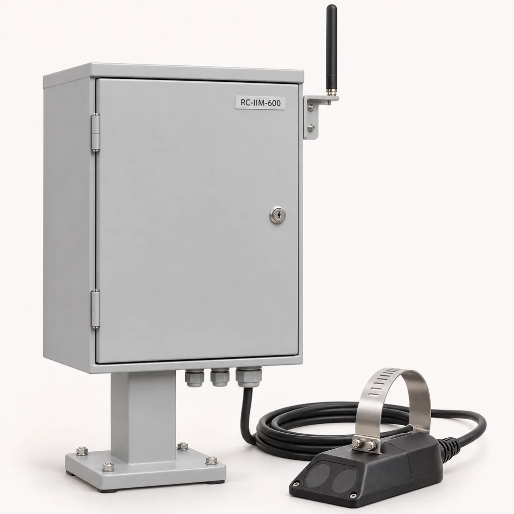
The RC-IIM-600 is a grid-powered sewer infiltration and inflow monitoring station for utilities, municipal asset owners, industrial estates, and engineering contractors. It combines submerged area-velocity measurement, rainfall records, local data logging, and a Web platform with a mobile app to show where wet-weather loading deserves investigation. Each station measures one or two pipe sections and reports water depth, signed velocity, calculated discharge, and separate forward and reverse volumes. REDCOAST.LTD provides the complete project solution, including an in-house acquisition and control PCB designed around the selected sensors and site interfaces. The operational need is established: utility programs use flow monitoring to assess infiltration and inflow and prioritize network improvements, as described in King County's flow monitoring program.
Key Features
- Direct depth and velocity measurement: A submerged ultrasonic Doppler sensor and pressure-based level channel provide the inputs for discharge calculation in partially filled pipes and qualified surcharge conditions.
- Rainfall-linked investigation: Compare rainfall, weekday and weekend flow profiles, event peaks, and recession periods to identify catchments requiring closer inspection.
- Signed flow accounting: Maintain separate forward, reverse, and net volume totals so backwater events remain visible in operational records.
- One or two measurement sections: Start with a single catchment outlet or monitor two nearby branches using independent geometry and calibration settings.
- Purpose-built electronics: REDCOAST.LTD designs the isolated acquisition, protected sensor interfaces, pulse counting, watchdog, and communications power-control circuitry at PCB level.
- Operation during network outages: Local calculations and scheduled recording continue while communications are unavailable; queued records upload after connectivity returns.
- Auditable data quality: Shallow water, weak acoustic returns, sensor faults, maintenance periods, and missing data carry explicit quality flags.
- Practical maintenance workflow: Web dashboards and the mobile app connect alarms, inspection photographs, cleaning records, and assigned work orders to the same asset.
Technical Architecture
The field assembly consists of a low-profile submerged velocity probe, a pressure level channel, a stainless steel mounting band or bracket, and an above-ground instrumentation cabinet. Each sensing chain includes its matched transmitter; proprietary probes require their manufacturer's interface rather than an assumed generic connection. The standard design covers circular pipes with internal diameters from 200 to 1,600 mm, subject to hydraulic suitability. Pressure spans of 0–3 m or 0–9 m are selected according to the maximum head above the pressure diaphragm. A local rain gauge or an existing timestamped rainfall feed supplies the rainfall record. An independent level sensor can be added where checking pressure drift or fouling justifies the extra channel.
The edge controller calculates discharge as Q = A(h) × v_mean. Surveyed pipe geometry, sensor elevation, sediment allowance, and a site-verified velocity relationship determine the wetted area and representative mean velocity; a local Doppler reading is not automatically the cross-sectional average. For example, a clean 600 mm circular pipe flowing half full has an area of approximately 0.1414 m², giving approximately 84.8 L/s at a verified mean velocity of 0.60 m/s. Once the pipe is full, the calculation uses the full effective cross-section and measured velocity; increasing pressure head does not increase pipe area. Reverse velocity produces a negative discharge while a separate totalizer records reverse volume. Entrained air, unstable flow profiles, heavy deposits, and insufficient acoustic reflectors can invalidate the result.
The controller acquires measurements every 10 seconds and normally stores one-minute aggregates with minimum, maximum, and quality information. The platform builds dry-weather profiles from operator-approved periods and compares them with wet-weather hydrographs, allowing for upstream travel time and operational changes. A rainfall-related excess volume is an investigation metric, not proof of a particular leaking joint or an automatic separation of groundwater infiltration from direct inflow. Unverified gaps are excluded from valid measured totals and marked incomplete; any estimated replacement series remains separate. This supports the continuing assessment approach documented in MWRA's FY2026 infiltration and inflow report, dated August 28, 2026.
Connectivity & Power
The RC-IIM-600 is intended for permanent urban and estate monitoring points with an available electrical service. Input is AC 100–240 V, 50/60 Hz, feeding an isolated 24 V DC supply. The proposed operating budget is 20–35 W for a typical station, with a 60 W electronics limit and an optional 50 W anti-condensation heater, giving a maximum configured input budget of 110 W. It includes no solar panel or onboard battery. Where continuity through mains interruptions is required, the site must provide an appropriately backed AC circuit; otherwise measurement stops and the outage is recorded as a data gap after restart.
Ethernet suits treatment works, pumping facilities, and sites with managed networks. An LTE Cat 1 or Cat 4 modem provides an alternative at roadside cabinets, with frequency bands and operator approval selected for the installation country. Antennas remain above ground rather than beneath a metal manhole cover. MQTT over TLS and HTTPS carry platform traffic; Modbus TCP or isolated RS-485 Modbus RTU connects to local SCADA. Modbus interfaces belong on a protected plant network, and remote access uses individual credentials and controlled permissions.
Protection & Reliability
The cabinet design targets IP66 with the door closed and the specified cable glands fitted. The standard enclosure uses hot-dip galvanized steel beneath a smooth matte powder-coated finish; a fluorocarbon topcoat is an alternative for demanding coastal exposure. Gasket condition, conduit sealing, protective earthing, surge protection, and installation above the design flood level are part of the installation specification. A sunshield and appropriate mounting position limit solar heat gain; the proposed ambient range of -20 to +55 °C applies to the configured assembly under the agreed thermal conditions. Salt exposure, windborne sand, and the local design wind inform the coating, seals, pedestal, and anchorage specification; environmental qualification uses the actual assembly.
Submerged components are selected for continuous immersion at the ordered 3 m or 9 m head rating, with chemically compatible wetted materials and factory-sealed cables. The cabinet's ingress rating does not qualify it for submersion, and an IP rating does not establish corrosion resistance or explosion protection. Conformal coating, replaceable surge devices, internal temperature and humidity monitoring, and a hardware watchdog support maintainability. Cleaning frequency and service life depend on grit, fats, chemical exposure, and hydraulic conditions; maintenance intervals are established from field inspection rather than an unsupported lifetime claim.
Application Scenarios
- Sanitary sewer catchment assessment: Install stations at accessible branch outlets with nearby mains service and pair them with representative rainfall records. Engineers can compare event response and baseflow trends to prioritize follow-up inspections.
- Rehabilitation verification: Retain monitoring upstream and downstream of a pipe-lining or connection-repair program. Compare suitable pre-work and post-work periods while accounting for rainfall, groundwater conditions, occupancy, and changes in the contributing network.
- Industrial estate wastewater management: Measure gravity sewer discharge from defined estate zones before flows combine. The records support capacity planning and investigation of unusual discharge patterns, without implying certified commercial billing.
- Backwater and surcharge investigation: Place a station at a hydraulically suitable section near a recurring surcharge location. Concurrent depth and signed velocity help distinguish rising water with ongoing conveyance from stagnation or reverse flow.
- Treatment works catchment planning: Monitor selected incoming branches to characterize their contribution to wet-weather peaks. Planners can use the time series alongside pump operation, storage, and treatment records when evaluating infrastructure options.
Case-style Examples
These examples illustrate proposed configurations and workflows; they are not claims of completed customer projects.
Residential catchment rehabilitation study. A utility wants to understand why two neighboring catchments respond differently during rainfall. Two RC-IIM-600 stations monitor separate 450 mm outlets, using mains connections, pressure-depth Doppler sensing, LTE uplinks, and a shared rainfall dataset whose coverage is checked for both catchments. A proposed six-week initial survey establishes usable dry-weather profiles and captures available storms; it is extended if the weather sample is insufficient. The resulting hydrographs help the team select locations for CCTV, smoke testing, or dye testing, with no promised percentage reduction before repairs are measured.
Industrial estate backwater investigation. An estate experiences intermittent high sewer levels near its connection to the public network. A two-section station records a 600 mm outlet and a nearby upstream branch, using Ethernet and an upgraded pressure span where the survey identifies higher surcharge head. Operators compare reverse-flow periods, rainfall, and discharge schedules to develop a defensible explanation of the event sequence. The expected deliverable is a quality-checked evidence package for hydraulic review, rather than an automatic diagnosis or an unverified capacity guarantee.
Customization & Selection Guide
Begin with pipe diameter and shape, invert and crown elevations, minimum dry-weather depth, peak surcharge head, sediment thickness, and access conditions. Select a straight, representative measurement section after reviewing nearby bends, drops, junctions, and pump discharges. A single submerged probe may be unsuitable where velocity profiles are strongly asymmetric; in that case, relocate the section or specify a validated profiling arrangement. Published submerged area-velocity sensor guidance demonstrates that sensor performance depends on installation conditions and the measurement profile.
For a limited budget, prioritize one well-surveyed measurement section, reliable rainfall coverage, and a clear maintenance plan. Add a second section, independent level cross-check, or higher pressure span only when it answers a defined operational question. The parameter table describes a proposed build-to-order configuration envelope: sensor accuracy, assembled enclosure performance, thermal capability, and site discharge uncertainty must be confirmed for the ordered configuration. The ±10% discharge comparison criterion is a proposed commissioning target under agreed stable-flow conditions, not a universal accuracy specification.
Deployment & After-sales
Deployment begins with a hydraulic survey, utility permissions, hazardous-area assessment, and confirmation of the mains and communications routes. Qualified personnel install the submerged sensing assembly under the applicable confined-space procedures, secure cables against debris and jetting damage, and locate the cabinet outside the classified area and above anticipated flooding. Commissioning verifies sensor elevation, pipe dimensions, pressure reference, clock synchronization, rain-gauge scaling, flow direction, alarm routing, and agreement with a suitable reference measurement over representative conditions.
Delivery scheduling separates configuration approval, PCB development where required, prototype verification, enclosure assembly, factory acceptance, and site acceptance. Standard-interface builds and new board designs receive different quotations and milestones; a fixed lead time is confirmed only after the sensor supply and verification scope are agreed. After-sales support covers configuration backups, remote diagnostics, firmware maintenance, spare modules, and operator training. Warranty duration, response times, calibration responsibilities, and damage exclusions are recorded in the project agreement, with routine cleaning and inspection procedures supplied at handover.
Standards & Compliance
Hydraulic method selection and installation review reference ISO 15769:2010, which addresses acoustic Doppler and echo-correlation velocity measurement in open channels and partially filled pipes. Surcharged operation additionally requires confirmation against the selected sensor's pressure rating and validated hydraulic application. The station is specified for operational assessment; regulatory reporting or custody-transfer use requires its own acceptance criteria and any applicable metrological approvals.
The conformity plan evaluates enclosure protection against IEC 60529, measurement and control equipment EMC against IEC 61326-1:2020, and applicable electrical safety requirements using IEC 61010-1 and its amendment. Destination-specific radio, material, and product conformity requirements are established for the ordered variant. These references define engineering and verification directions; they do not claim that an untested RC-IIM-600 assembly already holds certification.
Where a sewer is classified as hazardous, use appropriately certified sensing equipment and associated apparatus with documented cable and entity-parameter compatibility, assessed against the applicable requirements of IEC 60079-25:2020+A1:2025. The custom controller remains on the safe side of the approved interface; adding a barrier alone does not certify a sensing circuit. The delivered scope must match the site's zone, gas group, temperature class, and local requirements.
Why REDCOAST.LTD
REDCOAST.LTD develops complete outdoor IoT solutions that connect field equipment, management software, and daily maintenance workflows. Its in-house PCB and board-level design capability allows the acquisition channels, isolation, power distribution, connector layout, and communications interfaces to be engineered for the actual project. Selected specialist sensing elements can be combined with custom electronics without pretending that sensor certificates automatically cover the whole station. Buyers receive a coordinated hardware, firmware, Web platform, and mobile app scope with defined interfaces and a project-specific verification plan.
Contact REDCOAST.LTD with your pipe survey, expected flow and surcharge conditions, rainfall sources, and integration requirements to request a tailored RC-IIM-600 configuration.
Specifications
Hydraulic Measurement
- Independent measurement sections
- 1 standard; 2 optional sections
- Circular pipe internal diameter
- 200–1600; subject to hydraulic survey mm
- Specified velocity span
- -1.5 to +6.0; selected sensor must cover both directions m/s
- Pressure level span above sensor
- 0–3 standard; 0–9 optional m
- Minimum design water depth
- 50 above pipe invert; acoustic validity and probe geometry must also be satisfied mm
- Velocity sensor selection criterion
- ±2% of reading or ±0.02 m/s, whichever is greater, under the sensor's stated reference conditions
- Proposed site discharge comparison target
- ±10% of agreed reference under stable, suitable hydraulic conditions; acceptance test required
- Available totalizers
- 3: forward volume, reverse volume, net volume m³
Rainfall and Event Recording
- Optional tipping-bucket resolution
- 0.2 mm/tip
- Measurement acquisition interval
- 10 s
- Standard aggregate recording interval
- 60; includes minimum, maximum, mean, and quality flags s
- Rainfall aggregation interval
- 1 min
- Initial dry-weather profile window
- 28; uses approved valid periods and separate weekday/weekend profiles days
- Configurable alarm persistence
- 30–600 s
Custom Electronics and Field Interfaces
- Isolated analog inputs
- 4 channels, 4–20 mA, 16-bit conversion
- Isolated serial interfaces
- 2 × RS-485; Modbus RTU
- Pulse and status inputs
- 2 pulse counters plus 4 dry-contact inputs
- Alarm relay outputs
- 2 × SPDT; 2 A at 30 V DC resistive load
- Field sensor supply budget
- 24 V DC, 1 A total; 24 W aggregate maximum
- Analog transmission outputs
- 2 isolated 4–20 mA channels; maximum 500 Ω load
Mains Power
- Input voltage
- AC 100–240 V
- Input frequency
- 50/60 Hz
- Typical operating consumption
- 20–35; selected sensors, controller, display, and modem included W
- Maximum electronics input budget
- 60; excludes optional heater W
- Optional anti-condensation heater
- 50; thermostatically controlled W
- Maximum configured input budget
- 110; electronics and heater combined W
- Internal distribution voltage
- 24; isolated DC supply V DC
Communications and Data
- Ethernet
- 1 × RJ45, 10/100 Mbit/s
- Cellular modem options
- LTE Cat 1 or LTE Cat 4; country-specific band selection
- Application protocols
- MQTT over TLS 1.2 or later; HTTPS; Modbus TCP/RTU
- Local nonvolatile storage
- 8 GB
- Local retention configuration
- 365 at one-minute records for up to 16 numeric channels; rolling archive days
- Time reference
- UTC timestamps; NTP synchronization; separate clock-quality status
- Local service display
- 4.3; mounted inside the locked cabinet in
Enclosure and Environmental Design
- Cabinet dimensions
- 600 × 450 × 250; height × width × depth, excluding pedestal and sunshield mm
- Assembled cabinet ingress target
- IP66; final assembly verification required
- Submerged sensor ingress requirement
- IP68 with manufacturer-declared continuous immersion at 3 m or 9 m for the selected span
- Configured ambient design range
- -20 to +55; thermal verification with selected hardware and sunshield °C
- Liquid operating range
- 0 to +50; nonfreezing liquid °C
- Internal humidity design range
- 5–95, noncondensing % RH
- Cabinet corrosion protection
- Hot-dip galvanized steel substrate with smooth matte RAL 7035 powder coating; fluorocarbon topcoat option
- Standard sensor cable lengths
- 10, 20, or 30; factory-terminated cable matched to the sensing system m
Capabilities — configurable per project
Specifications are tailored to each project — the options below show what we can support.
Measurement Layout
- One catchment outlet
- Two nearby pipe sections with independent geometry
- One flow section with an independent level cross-check
Sensing Duty
- 0–3 m pressure span for assessed nonhazardous locations
- 0–9 m pressure span for higher surcharge head
- Certified hazardous-area sensing chain with matched associated apparatus and documented system assessment
Communications Route
- Ethernet to the existing plant network
- LTE Cat 1 cellular uplink
- LTE Cat 4 cellular uplink
- Fiber uplink through a cabinet media converter
Cabinet Installation
- Wall-mounted RAL 7035 powder-coated cabinet
- Pedestal-mounted cabinet with a sunshield
- Fluorocarbon-painted cabinet for a defined coastal exposure class
Software Delivery
- Hosted Web platform and mobile app
- Customer-hosted private deployment
- SCADA integration with historian export
Related solution guidance
Environmental Monitoring
Deploy environmental monitoring stations with sensors, solar power, gateways, dashboards, alarms and data integration for city and industrial sites.
Power and Connectivity
How to choose power, battery, solar, NB-IoT, LTE, LoRaWAN, gateways and monitoring strategy for outdoor IoT infrastructure.
Campuses
Campus IoT for lighting, parking, safety, smart poles, environmental data and facility maintenance workflows.
Frequently Asked Questions
What does a sewer infiltration and inflow monitoring station measure?
The RC-IIM-600 records water depth and signed velocity, calculates discharge from surveyed pipe geometry, and combines those records with rainfall. It reports forward, reverse, and net volumes with data-quality flags. Engineers use these records to investigate excess wet-weather loading and prioritize inspection or rehabilitation.
How is this different from a smart manhole level alarm?
A level alarm identifies water reaching a threshold, while this station also measures velocity and calculates flow through a defined pipe section. This helps distinguish rising water with continuing flow from stagnation or reversal. Reliable discharge measurement requires a suitable hydraulic location and a documented survey.
Can the RC-IIM-600 measure partially filled and surcharged sewer pipes?
Yes, the proposed sensing configuration covers partially filled pipes and qualified full-pipe surcharge conditions within the selected sensor's pressure and velocity limits. Under surcharge, the calculation uses the full effective pipe area rather than treating extra pressure head as additional area. Minimum immersion, acoustic signal quality, sediment, and entrained air can still limit valid measurement.
Can it identify the exact source of infiltration or guarantee a reduction in sewer overflows?
Flow and rainfall records can identify suspicious catchments and event patterns, but they do not locate a specific cracked joint or prove the source of every extra litre. CCTV, smoke testing, dye testing, groundwater observations, or hydraulic modeling may be needed. The system supports investigation and verification; it does not guarantee an overflow reduction.
Does this station require solar panels or an onboard battery?
No. This configuration uses AC 100–240 V, 50/60 Hz at permanent monitoring locations with electrical service and includes neither solar panels nor an onboard battery. If mains power fails, measurements stop unless the site supplies a backed AC circuit; the resulting interval is flagged as missing data.
What happens when cellular or internet connectivity is lost?
While mains power remains available, the controller continues local calculation and recording and retains a rolling archive configured for 365 days of one-minute records across up to 16 numeric channels. It uploads queued records after the link returns. Remote notifications are delayed during the outage, while configured local relay alarms remain available.
Can REDCOAST.LTD customize the PCB and supply the complete software system?
Yes. REDCOAST.LTD can develop the acquisition and control PCB, isolation, protected I/O, power distribution, enclosure interfaces, firmware, Web platform, and mobile app around the project requirements. Specialized flow probes retain their matched sensing electronics and applicable approvals. The final configuration receives its own verification plan, with hazardous-area interfaces and certification scope defined before manufacture.