Overview
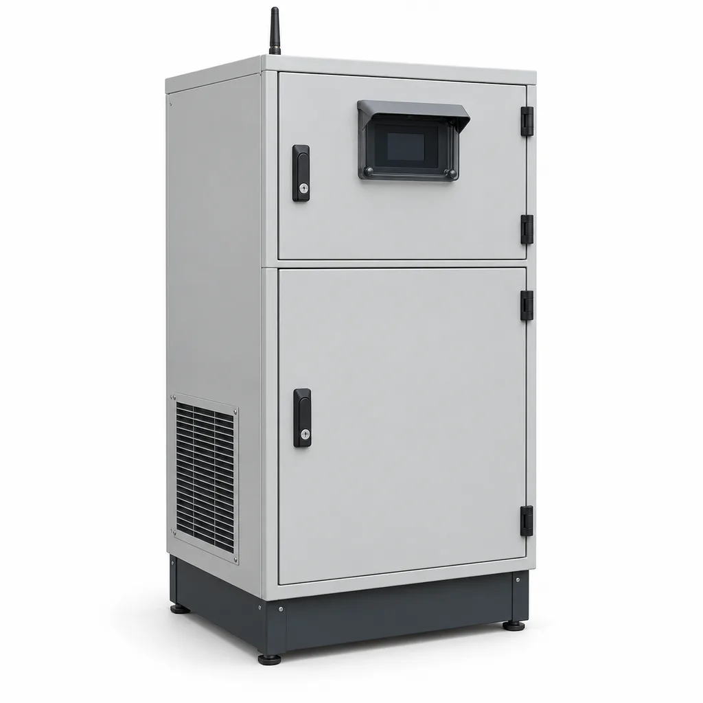
The RC-CSO-650 from REDCOAST.LTD is a mains-powered sewer overflow monitoring and refrigerated sampling station for utilities, municipal infrastructure operators, industrial estates, and environmental service contractors. It connects the time and duration of an overflow with identifiable physical samples that a laboratory can analyze after the event. Designed for accessible urban overflow structures and treatment-site bypass channels with a permanent electricity supply, it combines field instruments, automatic sampling, a Web management platform, and a mobile service app. REDCOAST.LTD develops the station controller, signal-conditioning circuits, pump-control electronics, and project-specific PCBs, allowing the complete workflow to match existing infrastructure and operating procedures.
Key Features
- Event-linked sampling: A surveyed overflow level or external event contact starts a defined collection program, linking every successful or failed collection to an event identifier and bottle position.
- Sequential or composite collection: The standard rack holds 24 one-liter bottles; alternative racks support 12 two-liter bottles or one 20-liter composite container.
- Refrigerated sample storage: A compressor-cooled compartment targets 4°C, with independent chamber and reference-bottle temperature records and configurable excursion alarms.
- Local operation during network loss: The controller executes sampling rules, records sensor quality, and retains data locally before forwarding queued records when communication returns.
- Hydraulic condition checks: Liquid detection, motor-current monitoring, purge routines, and limited retries help identify dry intakes, blocked hoses, and worn pump tubing.
- Operator-ready sample records: The platform associates collection time, programmed volume, bottle identity, temperature history, and pickup acknowledgment for laboratory handover.
- Survey-aware overflow records: Raw level observations remain separate from qualified events and reporting summaries, preserving the effects of threshold settings and data gaps.
- Hardware built around the project: Custom PCB layouts, isolated interfaces, cable entry arrangements, and firmware mappings support new stations and selected existing sampler mechanisms.
Technical Architecture
The field assembly comprises a non-contact radar level instrument, an intake strainer and suction hose, a reversible peristaltic pump, a bottle distributor, an insulated refrigerated compartment, and a separate electronics compartment. The REDCOAST.LTD controller combines isolated analog acquisition, digital event inputs, a real-time clock, motor-control interfaces, and nonvolatile storage. A replaceable communications module connects the station to the management platform. Purchased sensing elements and refrigeration components are integrated with the company's own board-level electronics; component certificates apply only to their stated scope.
The edge controller evaluates level against a surveyed overflow reference and applies commissioned confirmation and reset settings. On a qualified trigger, it checks available bottle capacity, advances the distributor, purges or rinses as configured, draws the programmed aliquot, and logs completion or failure. The baseline uses calibrated pump operation with liquid-arrival detection; a programmed dose is not an independently measured volume. Bottle fill limits are calculated from accumulated doses, with conservative headspace and local stop conditions. A full rack stops further collection and raises an alarm while event monitoring continues.
The platform displays event timelines, bottle status, refrigeration trends, maintenance history, and outstanding collection tasks. Operators can compare events with rainfall or flow data supplied by existing instruments. Event duration does not establish discharge volume, and neither duration nor level alone determines pollutant concentration or mass. Volume calculations require an appropriate flow measurement or a validated hydraulic relationship; pollutant loading additionally requires representative analytical results. Official monitoring guidance provides a useful reference for installation quality and operational records, while each project's reporting rules remain jurisdiction-specific. Event duration monitor installation and use guidance, updated 2024.
Connectivity & Power
Ethernet is the preferred connection where an operator already maintains a secure site network. An LTE Cat 1 module provides an alternative at roadside cabinets; its frequency bands and antenna are selected for the deployment country and carrier. MQTT over TLS and HTTPS connect to the platform, while Modbus RTU and Modbus TCP provide local integration with existing instruments and SCADA. Role-based access, individual device credentials, configuration histories, and controlled firmware updates form part of the specified software package. A private APN or customer-managed VPN can be incorporated into the network design.
The station uses permanent single-phase mains: the reference configuration is 220–240 VAC at 50 Hz, with a separately configured 110–120 VAC, 60 Hz version. Refrigeration, pump operation, enclosure heating, and optional intake heat tracing make continuous mains supply appropriate for these urban installations. The reference connected-load ceiling is 650 W, excluding compressor starting current; actual daily energy use depends on ambient temperature, sample temperature, and collection frequency. There is no standard backup supply: a power failure stops sampling and refrigeration, preserves committed records, and produces a data gap until restart. Continuous operation requires a separately engineered site emergency supply.
Protection & Reliability
The cabinet uses a hot-dip-galvanized steel substrate with a smooth matte powder-coated finish, a rain-shedding roof, lockable doors, and replaceable seals. The design targets IP65 for the sealed electronics compartment and IP54 for the complete outdoor station; these are distinct enclosure boundaries, and the station is not submersible. The condenser has a separate ventilated space so cooling airflow does not pass through the electronics. Coastal options change coating systems and exposed fasteners, while dusty locations require accessible condenser cleaning and inspection.
The reference ambient design range is -10 to +45°C in shaded installation. Freezing locations require a surveyed intake route, drain-back where practical, and the specified heat-trace package; an insulated cabinet alone cannot prevent an exposed suction line from freezing. Site-specific foundations and anchors address local wind loads, and the plinth must place the equipment above the assessed flood level. The baseline is for non-hazardous locations and non-flammable aqueous samples; hazardous-area sensors, barriers, and gas-migration controls require a separate installation assessment.
Serviceable pump tubing, door seals, fans, and refrigeration components support planned maintenance. Tubing replacement follows observed wear, pump usage, and dose checks rather than an unsupported universal service-life claim. Operating limits, enclosure ratings, and sampling performance in this product specification are design targets for the ordered configuration, to be confirmed through factory and site acceptance testing.
Application Scenarios
Combined sewer overflow structures. Install the cabinet beside an accessible overflow chamber with mains power and a surveyed spill reference. The station records event timing and collects a sequence of samples for investigating changes in wastewater characteristics during discharge.
Treatment-plant bypass channels. Connect to an existing bypass indication and verified flow signal. Operators can retain event-associated samples and review whether collection, refrigeration, and sample pickup remained within the agreed monitoring procedure.
Industrial estate discharge boundaries. Position the intake at a representative, well-mixed discharge point downstream of an estate's collection system. Scheduled or event-triggered samples help investigate intermittent changes, with analytical interpretation and any enforcement decision handled through the applicable laboratory and regulatory process.
Urban stormwater outfalls. At an accessible mains-served outfall, a rainfall contact or rising-level trigger can initiate an early-event sequence. Separate bottles preserve temporal differences that would be lost in a single combined sample, subject to intake wetting and actual pump response.
Storage-tank overflow investigations. Install at the defined overflow outlet of an existing detention or wastewater storage asset. Pairing discharge-event records with physical samples supports engineering investigations without changing the tank's gate or pump control system.
Case-style Examples
The following are illustrative configurations, not claims of completed customer installations or guaranteed results.
Urban overflow investigation. A utility needs to investigate intermittent spills that occur outside staffed hours. A station beside the overflow chamber uses one radar level instrument, LTE connectivity, and 24 one-liter bottles, taking one 250 mL aliquot into a fresh bottle every 15 minutes after the event trigger. The rack provides 24 time-separated samples, with 5 hours 45 minutes between the first and last collection; longer events require a different schedule or a bottle change. The intended benefit is a documented sample sequence that staff can retrieve after receiving an alert.
Treatment-site flow-proportional composite. An operator needs a sample representing a changing discharge flow rather than equal intervals of clock time. The station receives pulses from an existing verified flowmeter and places 100 mL aliquots into a 20-liter container, stopping at a configured 16-liter fill limit after 160 successful aliquots. Pulse scaling, minimum spacing between doses, and expected peak flow are checked during commissioning so the sampler can keep pace. The resulting composite supports the agreed laboratory method; the flowmeter remains responsible for the underlying flow measurement.
Customization & Selection Guide
Start with the analytical objective: time-resolved investigation favors separate bottles, while an approved average-concentration method may favor a composite. Identify analytes, required container materials, preservation procedures, pickup frequency, and laboratory holding times before choosing a rack. The standard HDPE bottles and general wastewater tubing are not a universal solution for volatile compounds, microbiology, trace metals, or PFAS. Refrigeration does not replace method-specific preservation, and warm incoming samples need a validated cooling period before reaching storage temperature. These distinctions follow the scope of ISO 5667-3:2024 on sample preservation and handling.
Next, measure vertical lift, hose length, bends, and the lowest expected water level. The proposed hydraulic envelope is up to 6 m lift with a 9 mm internal-diameter hose, but long hoses and high lifts reduce transport velocity and can change solids recovery. The reference volume-accuracy and velocity targets apply at no more than 3 m lift with a 10 m hose; the extremes of the broader installation envelope are not simultaneous guaranteed operating points. For context, established stationary samplers offer multi-bottle refrigeration and specify hydraulic performance against lift conditions. Teledyne ISCO 5800 manufacturer datasheet, revision 3.0, September 2023.
For a lower-cost installation, retain the 24-bottle rack, one level instrument, and Ethernet. Add a second confirmation input, LTE, intake heat tracing, or additional analog channels when the site's operating conditions justify them. Procurement specifications should distinguish the complete station, selected instruments, civil works, laboratory services, and any required third-party certification.
Deployment & After-sales
Deployment begins with a site survey covering mains availability, flood elevation, spill reference, radio coverage, intake representativeness, safe access, and authorized purge-water discharge. The installer anchors the cabinet to a concrete plinth, connects protective earth and supply protection, routes instrument and intake lines, and verifies the level reference. Commissioning includes measured dose checks at the installed lift, bottle-position verification, cooling tests with representative loads, communication-loss testing, and checks of alarms and restart behavior.
For planning, allow approximately 10–16 weeks from an agreed specification to a first engineering pilot using available major components. A new certification campaign, unusual refrigeration package, or major PCB redesign requires a separately confirmed schedule. Deliverables can include interface drawings, wiring schedules, configuration backups, calibration records, an acceptance checklist, and operator training. Remote diagnostics and replaceable controller modules support after-sales service; warranty duration, spare-parts coverage, and response times are defined in the supply agreement.
Standards & Compliance
The sampling plan should follow the applicable wastewater sampling method, with ISO 5667-10:2020 providing guidance on program design and representative wastewater sampling. EN 16479:2023 is a relevant performance and conformity-test reference for automatic water and wastewater samplers; the 2025 MCERTS sampler guidance identifies volume performance, transport velocity, sample integrity, timing, and environmental behavior as assessment areas. MCERTS certification should be specified where required by the procurement or regulatory regime, and is not claimed for this concept model.
The electrical assessment should address IEC 61010-1 safety requirements, applicable particular requirements, and IEC 61326-1:2020 EMC requirements. Enclosure testing should use IEC 60529. Destination-specific radio authorization, electrical marking, and restricted-substance documentation must be established for the delivered configuration. No whole-system certification, regulatory approval, or laboratory accreditation is implied by a component approval or a design reference.
Why REDCOAST.LTD
REDCOAST.LTD delivers the field station, operating software, Web platform, and mobile app as one coordinated solution. Its ability to design new PCBs and board-level hardware allows sensor inputs, pump interfaces, cabinet layouts, and service functions to be adapted to the customer's site and existing equipment. Project engineering can therefore address the complete sequence from detecting an event to collecting a sample, retrieving it, and reviewing its associated records.
Contact REDCOAST.LTD with your overflow geometry, available mains supply, sampling objectives, and integration requirements to configure an RC-CSO-650 station for your project.
Specifications
Overflow Event Monitoring
- Reference Level Instrument
- 80 GHz non-contact radar; 1 channel standard
- Configured Measurement Distance
- 0.3–8.0 m
- Level Accuracy Selection Target
- ±5 under selected sensor reference conditions; installed uncertainty assessed separately mm
- Local Level Acquisition Interval
- 5 s
- Event Confirmation Delay
- 0–60; set during commissioning s
- Reset Hysteresis
- 0–50; set against surveyed overflow geometry mm
- Event Timestamp Resolution
- 1; detection timing also depends on sensor response and 5 s acquisition s
Automatic Sampling Hydraulics
- Pump Arrangement
- 24 VDC reversible peristaltic pump with liquid-arrival detection
- Programmed Aliquot Volume
- 100–500 in 1 mL increments mL
- Suction Lift Envelope
- 0–6; reference performance conditions limited to 3 m
- Intake Hose
- 9 mm internal diameter; 3–15 m route length
- Transport Velocity Target
- At least 0.5 at up to 3 m lift with 10 m hose and clean water at 20°C m/s
- Volume Accuracy Target
- ±10% or ±10 mL, whichever is greater, after calibration at up to 3 m lift with 10 m hose and clean water at 20°C
- Timed Sampling Interval
- 5–1440; event and flow-pulse triggering also provided min
- Sampling Retries
- 0–3; failed collections logged separately
Bottle Storage & Refrigeration
- Standard Bottle Rack
- 24 × 1 L HDPE bottles
- Alternative Bottle Racks
- 12 × 2 L HDPE or 1 × 20 L HDPE
- Reference Fill Limit
- 800 per 1 L bottle; configurable for the chosen analytical method mL
- Sample Storage Temperature Target
- 4 ±2 after validated cooldown; reference ambient 25°C and 250 mL collection every 15 min °C
- Temperature Monitoring
- 2 channels: chamber air and liquid-filled reference bottle
- Reference Temperature Measurement Target
- ±0.5 across 0–10°C after calibration °C
- Temperature Logging Interval
- 60 s
Connectivity & Software
- Ethernet Port
- 1 × 10/100BASE-T
- Cellular Option
- LTE Cat 1; country-specific band configuration and external antenna
- Cloud Interfaces
- MQTT over TLS 1.2 or later; HTTPS REST API
- Local Integration
- Modbus RTU and Modbus TCP
- Normal Upload Interval
- 15–900; default 60, network permitting s
- Local Storage
- 16 GB industrial flash; minimum 90 days at 5 s logging for 20 numeric channels
- Management Interfaces
- Web dashboard; Android/iOS service app; CSV/JSON data export
- Access Roles
- Viewer, operator, administrator; individual accounts and configuration audit log
Custom PCB & Field Interfaces
- Analog Inputs
- 4 isolated 4–20 mA channels, 16-bit conversion
- Digital Inputs
- 8 dry-contact channels, including 2 pulse-counting inputs
- Relay Outputs
- 4 dry contacts; maximum 30 VDC, 1 A resistive per contact
- Serial Interfaces
- 2 isolated RS-485 ports
- Pump Motor Channel
- 1 reversible 24 VDC channel; up to 5 A continuous design rating
- Distributor Positions
- 24 indexed positions with home-position feedback
- Local Operator Display
- 4.3-inch color display behind lockable weather cover
Grid Power
- Reference Mains Input
- 220–240 VAC, single phase, 50 Hz
- Alternative Factory Electrical Version
- 110–120 VAC, single phase, 60 Hz
- Electronics & Level Sensor Load
- 15–25; excludes pump, refrigeration, heaters, and trace heating W
- Connected-Load Design Ceiling
- 650 including selected heating options; excludes compressor starting current W
- Intake Heat-Trace Option
- 10 W/m over a maximum 10 m heated section; route-specific freeze assessment required
- Supply Protection
- Lockable isolator, branch overcurrent protection, Type 2 surge protection, protective earth
- Power-Loss Behavior
- Sampling and refrigeration stop; committed data retained; restart and gap recorded
Protection & Installation
- Electronics Compartment Protection Target
- IP65 with doors closed and specified glands fitted
- Complete Station Protection Target
- IP54; above-flood installation, non-submersible
- Ambient Design Range
- -10 to +45 in shade; subzero operation requires intake freeze protection °C
- Sample Inlet Temperature
- +2 to +35; cooldown validated for the selected collection program °C
- Reference Cabinet Dimensions
- 1450 × 800 × 800, H × W × D; excludes plinth and antenna mm
- Cabinet Finish
- Hot-dip-galvanized steel with smooth matte powder coating; RAL 7035 standard
- Mounting & Access
- Concrete plinth; minimum 800 mm front service clearance and 300 mm condenser-side clearance
- Installation Classification
- Non-hazardous area; non-flammable aqueous samples
Capabilities — configurable per project
Specifications are tailored to each project — the options below show what we can support.
Sampling Configuration
- 24 × 1 L sequential rack
- 12 × 2 L sequential rack
- 1 × 20 L composite container
Event & Sampling Trigger
- Surveyed radar level threshold
- External dry-contact event input
- Verified flowmeter pulse input
- Rainfall input with level qualification
Platform Connection
- Ethernet to customer network
- LTE Cat 1 with selected carrier bands
- Ethernet plus LTE failover
Climate & Cabinet Package
- Shaded temperate installation
- Intake heat tracing for freezing conditions
- Coastal coating and exposed-fastener upgrade
Software Deployment
- Managed cloud platform
- Customer private cloud
- On-premises server with SCADA integration
Related solution guidance
Environmental Monitoring
Deploy environmental monitoring stations with sensors, solar power, gateways, dashboards, alarms and data integration for city and industrial sites.
Ports and Logistics
Outdoor IoT infrastructure for ports, yards and logistics areas: lighting, guidance, safety, solar power, monitoring and maintenance visibility.
Power and Connectivity
How to choose power, battery, solar, NB-IoT, LTE, LoRaWAN, gateways and monitoring strategy for outdoor IoT infrastructure.
Frequently Asked Questions
How is this station different from a smart manhole sensor?
A smart manhole sensor typically reports level, cover movement, or gas conditions. The RC-CSO-650 adds a mains-powered refrigerated sampler that retains identifiable physical samples associated with an overflow event. Laboratory analysis can then complement the event record; the station itself does not measure every pollutant.
Does recording overflow duration also measure discharge volume?
No. Event duration describes how long the configured overflow condition was detected. Discharge volume requires a suitable flow measurement or a validated relationship between measured level and discharge, with backwater and other hydraulic limitations considered. Pollutant mass additionally requires representative concentration results.
Can the station collect samples proportional to wastewater flow?
Yes, the specified controller accepts pulses from a verified flowmeter and can request a fixed aliquot after each configured volume increment. Commissioning must check pulse scaling, pump cycle time, and peak flow so sampling requests do not exceed physical collection capacity. Missed or deferred requests are recorded, and the program stops when the configured container limit is reached.
How many samples can the standard 24-bottle rack collect?
The standard rack provides 24 separate one-liter bottles. With one 250 mL aliquot per bottle every 15 minutes, it provides 24 discrete samples, with 5 hours 45 minutes between the first and last. A composite program can place multiple aliquots in a bottle up to its configured fill limit, but the laboratory method and holding time determine whether that program is appropriate.
Does a 4°C refrigeration setting guarantee that every sample is preserved?
No. Incoming liquid takes time to cool, and chamber air temperature is not the same as the temperature of every collected sample. The specification includes chamber and reference-bottle logging, but the selected workload must undergo cooling validation. Container materials, chemical preservation, transport conditions, and holding times still follow the analytical method.
What happens if the mobile network or mains supply fails?
With mains power available, network loss does not stop the local sampling program; records remain in local storage for later upload. A mains outage stops both sampling and refrigeration because the baseline station has no backup supply. Previously committed records are retained, the gap is marked after restart, and affected samples require review against their temperature and holding-time requirements.
Can REDCOAST.LTD redesign the hardware for an existing sampler or SCADA system?
Yes. REDCOAST.LTD can develop project-specific controller, isolated input, pump-driver, and interface PCBs together with matching firmware and platform mappings. Existing mechanisms require documented electrical and mechanical interfaces before compatibility can be confirmed. Hardware changes may require fresh performance testing and reassessment of any applicable certification scope.
Is the RC-CSO-650 already certified for regulatory sampling or hazardous sewer locations?
This product package defines a configurable concept specification and does not claim an existing whole-station certificate. Regulatory sampling projects must identify their required approvals, analytical methods, and acceptance tests before procurement. The baseline cabinet is for non-hazardous locations; a classified sewer interface requires appropriately selected certified equipment and a site-specific installation assessment.