Overview
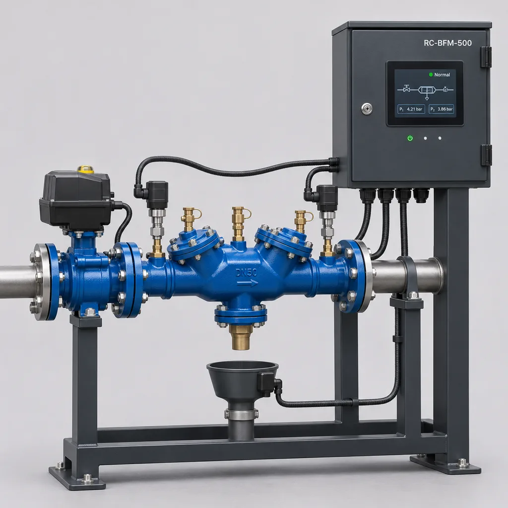
The RC-BFM-500 Smart Backflow Preventer Monitoring & Flood Shutoff Station is a mains-powered water-service supervision solution from REDCOAST.LTD for public landscapes, campuses, sports facilities, and managed commercial estates. It detects sustained discharge from a reduced pressure zone backflow preventer, rising water at the drain receptor, and abnormal service conditions, then alerts operators and closes an upstream isolation valve where branch isolation is authorized. The reference package combines a field controller, discharge and drain sensors, two pressure transmitters, a pipe-temperature probe, an actuated valve, and a Web platform with mobile App access. REDCOAST.LTD develops the controller electronics and project-specific PCB interfaces, while the mechanically certified backflow assembly is selected separately for the actual water hazard and installation requirements.
Key Features
- Discharge-specific monitoring: Separate inputs identify relief discharge and a high-water condition at the drain receptor, helping operators distinguish a brief discharge from a developing drainage problem.
- Local automatic isolation: The controller executes its commissioned shutdown sequence without an internet connection and checks independent valve-open and valve-closed limit switches.
- Adjustable persistence filtering: A 0–60 second continuous-discharge timer allows commissioning around normal operating events; an independent high-water input can initiate a faster response.
- Irrigation coordination: A hardwired run-permit contact inhibits the irrigation controller or booster-pump request before valve closure, with the sequence agreed against the downstream equipment.
- Useful service measurements: Two 0–16 bar pressure transmitters and a contact temperature probe support maintenance decisions, low-pressure alerts, and seasonal freeze-risk notification.
- Accessible maintenance: Key-controlled service mode, a visible bypass indication, sensor fault reporting, and recorded operator actions support supervised inspection and testing.
- Open integration: Ethernet, isolated RS-485, Modbus, and optional LTE Cat 1 connect the station to existing building, irrigation, and estate-management systems.
- Project-specific electronics: REDCOAST.LTD can redesign signal conditioning, isolated inputs, valve interfaces, terminal layouts, and firmware on a dedicated PCB when a standard panel would create unnecessary wiring or interface compromises.
Technical Architecture
The reference build supervises one DN50 irrigation service branch. Its hydraulic arrangement places a motorized isolation valve upstream of the approved RPZ assembly, followed by the irrigation service. Pressure transmitters connect to dedicated, approved pipe takeoffs around the RPZ assembly; routine testing ports remain accessible. A discharge sensor mounts in a compatible open drain receptor or downstream of the manufacturer's air-gap fitting without reducing the required opening. A separate high-water sensor detects water accumulating at the receptor. The controller does not alter the mechanical check valves, relief valve, or atmospheric separation that provide backflow protection.
Inside the cabinet, a REDCOAST.LTD microcontroller board handles isolated 4–20 mA acquisition, temperature measurement, supervised alarm circuits, valve command outputs, and hardware watchdog functions. A separate communications process publishes measurements and alarms, so cloud availability does not determine whether a local event is recognized. Pressure readings are acquired once per second, while contact inputs are scanned every 100 milliseconds. The standard recorder stores one-minute trends, event timestamps, sensor faults, operator actions, and valve feedback. Pressure trends describe service conditions; they do not constitute a certified differential-pressure test of the RPZ checks.
In automatic mode, sustained discharge beyond the selected delay or a confirmed high-water event latches an alarm, removes the downstream run permit, and starts the approved isolation sequence. The reference actuator completes its stroke in approximately 30 seconds under its specified operating conditions; 20–60 second actuators are selectable after hydraulic review. Missing closed-position feedback produces a separate closure-failure alarm rather than a successful-shutdown indication. Reopening requires an authorized local reset after inspection. Stored alarm latches survive a controller restart, and sensor faults remain distinguishable from a confirmed water event.
Connectivity & Power
The station uses AC 100–240 V, 50/60 Hz from the permanent electrical supply at the irrigation service enclosure or plant area. This matches its normal deployment beside existing building and landscape infrastructure. Monitoring consumption is approximately 10–18 W; the internal 24 V DC field supply provides an aggregate 60 W budget for compatible sensors and the actuator. A 40 W cabinet anti-condensation heater is optional, and the complete reference electrical configuration remains within a 150 W maximum input allowance. The cabinet heater does not protect exposed water pipes from freezing.
Ethernet is the preferred connection where a facility network is available. LTE Cat 1 provides an alternative for outdoor locations lacking a data cable, with the modem bands and carrier subscription selected for the installation. Isolated RS-485 supports Modbus RTU; Ethernet supports Modbus TCP and MQTT over TLS for telemetry. Modbus access belongs on a segregated controls network. The platform provides site maps, alarm acknowledgement, trend exports, maintenance records, and role-based access through the Web interface and App.
During a network outage, local detection and control continue while records queue for later upload. During loss of mains power, the standard non-spring-return actuator remains at its last position, active sensing stops, and no new powered closure can be guaranteed. The run-permit relay drops out, allowing a correctly wired downstream controller to inhibit operation. A missing-heartbeat notification can be raised by the platform, but it cannot distinguish a power outage from a failed network connection without other evidence.
Protection & Reliability
The proposed enclosure specification is IP66 with sealed cable glands, a gasketed door, segregated mains terminals, and protective earthing. The electronics design envelope is -20 to +55 °C; wetted components operate with liquid water at +5 to +40 °C in the reference configuration. These limits are separate: an electronics cabinet that operates below freezing does not make an unheated RPZ assembly suitable for freezing water. Cold sites require a separately sized heated hydraulic enclosure or an approved seasonal drain-down procedure.
The cabinet and mounting frame use a corrosion-protected galvanized base with a smooth matte powder-coated finish. Coastal projects can specify a fluorocarbon topcoat, compatible fasteners, and a documented coating inspection plan. Dust, direct sunlight, condensation, and washdown exposure are assessed at the installed assembly; a sunshield is recommended for exposed hot locations. Pedestal anchoring is calculated for local wind and mounting conditions. The product is mounted above anticipated standing water and is not a submersible controller.
Replaceable terminals, sensor connectors, power supplies, and actuator assemblies support field repair. Warranty duration, spare-part availability, and maintenance obligations are stated in the project quotation. Environmental ratings are design targets until verified on the ordered assembly; no universal salt-spray life, maintenance-free service life, or completed certification is implied.
Application Scenarios
Public park irrigation service entrances. Install the station beside the above-ground RPZ enclosure feeding landscape irrigation. Sustained relief discharge can be reported and the dedicated irrigation branch isolated, helping crews address a fault before it causes prolonged water loss or erosion.
University and corporate campuses. Multiple monitored service entrances report to one estate-management dashboard. Facilities teams can identify the affected branch, see whether closure was confirmed, and coordinate maintenance without manually checking every enclosure.
Sports grounds and stadium landscapes. A service-entry fault near paths, equipment stores, or spectator circulation areas requires a clear operational response. The station coordinates its isolation request with the irrigation controller and records the event for groundskeeping staff.
Commercial and hospitality landscapes. Irrigation equipment often sits behind screening or in service yards where discharge is not immediately visible. Remote notification and a dedicated branch valve help maintenance teams respond while preserving unaffected water services.
Municipal maintenance compounds. Non-critical washdown or landscape branches can share a supervision platform while retaining individual isolation decisions. The mechanical backflow assembly and automatic-shutdown policy are selected for each branch's water hazard and operational needs.
Case-style Examples
The following are illustrative engineering scenarios, not claims of completed customer installations.
Campus irrigation enclosure retrofit. A campus has an existing DN50 RPZ assembly, an adequate open drain, and mains power but no nearby data cable. The proposed package adds discharge and receptor sensors, two pressure transmitters, an upstream motorized valve, and LTE telemetry. Commissioning verifies a 15-second discharge persistence setting, the actuator's approximately 30-second stroke, and local reset behavior; the intended result is an identifiable alarm and a verified branch-isolation sequence.
Sports-ground service upgrade. A venue operates a downstream booster pump and wants a discharge fault to stop irrigation in a controlled order. The design uses Ethernet, a hardwired pump run-permit interlock, and valve-closure timing established from the actual pipe network. Acceptance testing checks that the pump response and pressure behavior are suitable before automatic isolation is enabled.
Commercial estate monitoring deployment. Several service branches require notifications, but one essential branch cannot be automatically interrupted. That location receives the monitoring-only configuration, while suitable irrigation branches receive actuated isolation. Operators gain a consistent view of discharge events and equipment condition without assigning the same shutdown policy to every supply.
Customization & Selection Guide
Start with the existing backflow assembly's make, model, approval, size, installation orientation, and manufacturer discharge curve. Confirm that an RPZ or Type BA device is appropriate for the actual hazard; applications requiring an air gap retain that requirement. The RC-BFM-500 does not change the required protection category or replace periodic inspection and assembly testing.
For the reference DN50 branch, use 6–12 m³/h as a preliminary demand envelope, then verify residual downstream pressure using the selected RPZ and isolation-valve loss curves. DN25–DN80 valve packages are available as project configurations. The system's maximum working pressure is the lowest applicable rating of every installed wetted component, with a 10 bar reference ceiling.
Drainage must accommodate the selected assembly's possible discharge independently of the electronic shutoff. Preserve the specified air gap and never cap or restrict the relief outlet. As an illustrative calculation, a sustained 2 L/s discharge lasting 45 seconds releases 90 L before additional pipe drain-back; an alarm and closing valve therefore do not remove the need for drainage. Manufacturer guidance calls for checking actual discharge, drain behavior, and closing speed during commissioning. Watts LFF113FP installation instructions, 2025 revision.
Choose monitoring-only operation where interruption is unacceptable. Automatic isolation in this product is intended for approved irrigation and other non-critical branches, not fire-service supplies. Select Ethernet for an existing controls network, LTE for locations without data cabling, and additional floor-leak or temperature inputs where site conditions justify them. A new PCB design is appropriate when a fleet requires different sensor interfaces, actuator loads, enclosure dimensions, or a standardized installation harness.
Deployment & After-sales
Before manufacture, REDCOAST.LTD reviews a piping schematic, assembly photographs, peak demand, operating pressure, drain capacity, power availability, connectivity, and the required shutdown sequence. The delivery scope identifies which hydraulic components are supplied new and which remain existing assets. Installation drawings preserve access to test cocks, isolation handles, the relief outlet, and replaceable sensors.
Factory acceptance covers input simulation, circuit-fault detection, alarm timing, output behavior, restart handling, and communications. Site acceptance adds controlled wet testing, actual valve travel, downstream pump response, drainage observation, and loss-of-network and loss-of-power checks. A qualified installer performs hydraulic work, and backflow testing follows the applicable local procedure. The handover package includes terminal drawings, an I/O schedule, firmware identification, alarm settings, calibration information, and operator instructions.
Lead time is quoted after the valve selection and interface specification are agreed. A new PCB, enclosure tooling, or additional laboratory testing adds explicit engineering milestones before production release. After-sales support covers remote diagnostics, replacement controller and sensor kits, firmware maintenance, and technician training. Periodic sensor cleaning, wet-function tests, valve exercise, and inspection of drainage and coatings remain part of ownership.
Standards & Compliance
Mechanical backflow assemblies are selected against the applicable approval route, such as ASSE 1013 or EN 12729 for the relevant reduced-pressure assembly type. Installation selection also follows the applicable cross-connection risk assessment, including EN 1717 where adopted. These standards govern particular devices and installation conditions; they do not certify the monitoring controller or make one assembly suitable for every water hazard. EN 1717 scope, ASSE product standards, and BSI EN 12729 scope.
For drinking-water-contact components, procurement specifies the locally accepted material approvals, with NSF/ANSI/CAN 61 where required. Its scope addresses substances introduced into drinking water by materials and components, rather than proving flood-control performance. NSF explanation of Standard 61.
The electrical verification plan uses IEC 60529 for enclosure ingress protection and the applicable measurement-and-control safety and EMC requirements, including IEC 61010-1 and IEC 61326-1 where appropriate. Regional electrical, radio, and substance restrictions are included in the ordered configuration's compliance matrix. Certificates, declarations, and test reports must identify the actual supplied hardware. IEC 60529, IEC 61010-1, and IEC 61326-1.
Why REDCOAST.LTD
REDCOAST.LTD delivers the complete supervision solution: field hardware, embedded control, communications, the Web platform, mobile App workflows, installation documentation, and integration support. In-house PCB and board-level design allow the project to change its sensor interfaces, isolation arrangement, actuator controls, and connector layout without being limited to a fixed collection of third-party modules. Approved mechanical backflow components remain identifiable within that solution, while REDCOAST.LTD develops the electronics and software that connect their operation to the customer's maintenance process.
Send REDCOAST.LTD your backflow assembly details, service pressure, peak flow, drainage arrangement, and control requirements to request a customized RC-BFM-500 configuration.
Specifications
Hydraulic Integration
- Supervised service branches
- 1 per controller
- Reference valve size
- DN50
- Selectable nominal pipe sizes
- DN25, DN32, DN40, DN50, DN65, DN80
- Reference maximum working pressure
- 10; lower component rating governs bar
- Reference DN50 design flow
- 6–12; verify against selected assembly pressure-loss curves m³/h
- Reference water temperature
- +5 to +40; liquid water only °C
- Hydraulic connection options
- DN25–DN50: BSP or NPT threaded; DN65–DN80: PN16 flanged
Sensors & Acquisition
- Included pressure transmitters
- 2 × 0–16 bar, 4–20 mA
- Pressure transmitter accuracy target
- ±0.5% of full scale at +23 °C
- Analog input capacity
- 4 × isolated 4–20 mA
- Digital input capacity
- 8 total: 6 isolated contact inputs and 2 supervised alarm loops
- Water-event sensors
- 1 relief-discharge wet/dry sensor and 1 drain-receptor high-water sensor
- Temperature input capacity
- 2 × Pt1000; 1 pipe probe included; measurement range -20 to +80 °C
- Temperature channel accuracy target
- ±1 over 0 to +50 °C, excluding mounting error °C
- Acquisition intervals
- Pressure: 1 s; digital inputs: 100 ms
Local Control & Isolation
- Continuous-discharge persistence setting
- 0–60 in 1-second steps; reference commissioning value 15 s
- High-water input debounce
- 1–5; reference commissioning value 2 s
- Reference actuator electrical rating
- 24 V DC; 40 W maximum; non-spring-return
- Selectable full-stroke time
- 20–60; reference 30 under specified actuator conditions s
- Valve closure timeout setting
- 30–180; must exceed verified travel and interlock delay s
- Valve position feedback
- 2 independent end switches: fully open and fully closed
- Relay interface outputs
- 4 × dry contact, 30 V DC / 1 A resistive maximum; external actuator interface as specified
- Operating and reset modes
- Monitor / Auto / keyed Service; latched shutdown; authorized local reopening
Mains Power
- Input voltage
- AC 100–240 V
- Input frequency
- 50/60 Hz
- Monitoring power consumption target
- 10–18; actuator idle and heater off W
- Field power output budget
- 24 V DC, 2.5 A maximum aggregate; 60 W shared by sensors and actuator
- Optional cabinet anti-condensation heater
- 40; cabinet only, excludes hydraulic pipe heating W
- Complete controller input allowance
- 150 maximum, including field loads and cabinet heater W
Connectivity & Software
- Ethernet interface
- 1 × 10/100BASE-T
- Serial interface
- 1 × isolated RS-485; 1,200–115,200 baud
- Optional cellular modem
- LTE Cat 1; project-selected bands and carrier SIM
- Integration protocols
- Modbus RTU, Modbus TCP, MQTT over TLS, HTTPS API
- Trend logging interval
- 10–900; default 60 s
- Local storage design
- 128 MB; at least 180 days at 60-second intervals for 8 numeric channels, plus 10,000 events
- Access and update controls
- Administrator / Operator / Viewer roles; unique device credentials; signed firmware updates
- Platform delivery
- Hosted or on-premises Web platform with mobile App; CSV export and alarm acknowledgement
Protection & Mechanical Design Targets
- Controller enclosure ingress protection
- IP66; verification required on completed assembly
- Electronics ambient temperature
- -20 to +55; installation thermal assessment required °C
- Operating humidity
- 5–95, non-condensing % RH
- Controller cabinet dimensions
- 400 × 300 × 200, H × W × D; excludes brackets mm
- Controller cabinet mass
- 9–12; excludes hydraulic assembly and pedestal kg
- Cabinet and frame finish
- Galvanized steel base with smooth matte powder coat; RAL 7016 or RAL 7035
- Mounting arrangement
- Wall or pedestal; 4 × M8 fixing points; installed above standing-water level
- Reference hydraulic equipment location
- Above-ground, accessible enclosure with open relief drainage; separate freeze protection where required
Capabilities — configurable per project
Specifications are tailored to each project — the options below show what we can support.
Delivery Scope
- Monitoring-only retrofit for an existing approved RPZ or Type BA assembly
- DN50 reference station with 24 V DC motorized upstream isolation
- DN25–DN80 engineered valve package with documented component selection
Communications
- Ethernet and isolated RS-485
- Ethernet with LTE Cat 1 cellular fallback
- Ethernet connected through the customer's external fiber uplink
Additional Sensing
- 2–10 m floor-leak detection cable with interface module
- Second Pt1000 probe for enclosure or pipe temperature
- Additional 4–20 mA pressure or level transmitter
Environmental Package
- Standard sheltered outdoor cabinet
- Sunshield and smooth powder-coated pedestal
- Coastal fluorocarbon topcoat and compatible corrosion-resistant fasteners
- Separately engineered heated hydraulic enclosure for freezing climates
Software & Board-Level Engineering
- Hosted Web platform and mobile App
- On-premises Web platform and mobile App
- BMS or irrigation-platform integration using documented registers and API
- Custom PCB terminal layout, sensor front end, and actuator interface
Related solution guidance

Environmental Monitoring
Deploy environmental monitoring stations with sensors, solar power, gateways, dashboards, alarms and data integration for city and industrial sites.
Solar IoT Guide
A design guide for solar-powered outdoor IoT: load calculation, battery autonomy, low-power firmware, telemetry and maintenance planning.
Solar Off-Grid IoT
Design solar-powered outdoor IoT systems with panels, batteries, controllers, low-power devices, gateways and remote power monitoring.
Frequently Asked Questions
What does a smart backflow monitoring station add to an RPZ assembly?
The RC-BFM-500 detects relief discharge, drain-receptor high water, and service conditions, then sends alarms and executes an authorized upstream isolation sequence. The mechanical RPZ assembly remains responsible for backflow protection. Electronic readings and alarm history do not replace the assembly's required inspection or certified field testing.
Can RC-BFM-500 be fitted to an existing backflow preventer?
A retrofit is possible after checking the assembly model, relief outlet, air-gap fitting, drainage, available pipe space, and approved sensor attachment method. The package can preserve the existing mechanical assembly while adding sensors, a controller, and an upstream isolation valve. Compatibility is confirmed from drawings and manufacturer requirements rather than assumed across all brands.
Does every irrigation supply need an RPZ or Type BA backflow preventer?
No single device type is correct for every installation. The water supplier's requirements, downstream contamination hazard, possible backpressure, and applicable installation rules determine the required protection. Where a physical air gap is required, this monitoring station does not make an RPZ assembly an acceptable substitute.
What happens if the internet connection or mains power fails?
An internet outage does not stop local monitoring or commissioned isolation logic; records are buffered for later upload. Loss of mains power stops active monitoring, and the standard non-spring-return valve remains at its last position, so a new closure is not guaranteed. The run-permit relay drops out, and the platform can report a missing heartbeat without claiming to know whether power or communications failed.
How quickly can the station stop a relief-valve discharge?
The configurable discharge timer is 0–60 seconds, followed by any required interlock sequence and actual actuator travel. The reference selection uses a 15-second timer and approximately 30-second valve stroke, but these are commissioning values rather than a universal stop-time guarantee. High-water detection has a separate 1–5 second debounce, and every closure must be confirmed by position feedback.
Is a drain still necessary if an automatic shutoff valve is installed?
Yes, the drain must accommodate the selected backflow assembly's potential discharge independently of the shutdown system. Water can continue flowing during detection and valve travel, and downstream pipework can release additional water afterward. The relief outlet and required air gap must remain unobstructed, and drain sizing uses the actual manufacturer's discharge data.
Can this station operate outdoors in freezing or coastal conditions?
The controller has a proposed -20 to +55 °C electronics envelope and an IP66 enclosure target, with coating and sunshield options for the site. The reference wetted equipment requires liquid water at +5 to +40 °C, so freezing climates need a separately engineered heated hydraulic enclosure or seasonal drain-down. The optional 40 W cabinet heater manages the electronics enclosure and is not a pipe freeze-protection system.
What information is needed for a project quotation?
Provide the backflow assembly make and model, pipe size, operating pressure, peak flow, drainage arrangement, power supply, and network availability. Also identify downstream pumps, the permitted shutdown sequence, and any service that must remain operational. REDCOAST.LTD then defines the hydraulic package, sensor set, custom PCB requirements, Web/App integration, acceptance tests, and delivery milestones.