Overview
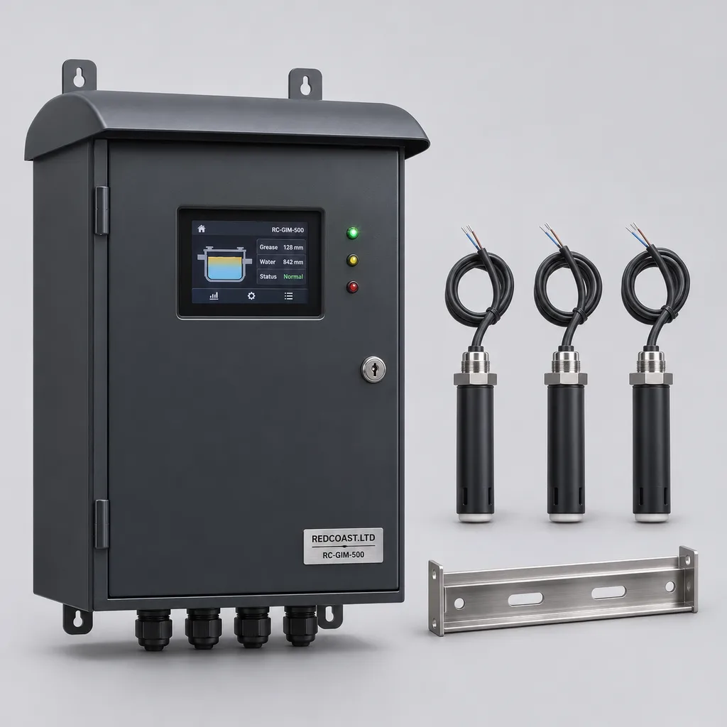
The RC-GIM-500 is a smart grease interceptor monitoring and pump-out management station from REDCOAST.LTD for commercial kitchens, campuses, transport terminals, hospitality properties, and public facilities. It connects grease accumulation alarms, high-liquid warnings, equipment diagnostics, and service records in one hardware, Web platform, and mobile App solution. Facility teams can distinguish a separator approaching its service threshold from an urgent hydraulic problem, assign the appropriate contractor, and retain an auditable maintenance history. The reference configuration uses an existing AC supply beside the building or service yard; it is a build-to-order product specification, with final ratings and acceptance tests agreed for each project.
Key Features
- Two grease alarm stages: Separate capacitive point probes provide an early service warning and a higher accumulation alarm at independently commissioned elevations.
- Dedicated high-liquid detection: A third probe detects liquid reaching an abnormal elevation, with its own alarm priority and confirmation timer.
- Local operation during network outages: The edge controller maintains sensing, audible indication, display messages, and alarm relay operation while storing records for later upload.
- Pump-out workflow: Operators assign work orders, attach contractor receipts and photographs, record sludge inspections, and confirm probe cleaning and water refill.
- Purpose-built electronics: REDCOAST.LTD develops the probe interface, cable supervision, isolated I/O, and power-monitoring PCBs to suit the selected sensors and site interfaces.
- Building-system integration: Ethernet, isolated RS-485, Modbus, and dry contacts connect the station to facilities management and existing alarm panels.
- Outdoor serviceability: A finished metal cabinet, removable probe rail, accessible terminals, and replaceable field cables support maintenance from the access opening.
- Clear data quality: Disconnected probes, stale communications, maintenance mode, and unconfirmed service completion remain visible instead of appearing as normal operation.
Technical Architecture
One station monitors one gravity grease interceptor using two grease-in-water point detectors and a separate high-liquid detector. Grease probes sit at different elevations in the separation compartment, away from inlet turbulence, baffles, and the pump-out hose path. Their capacitance response changes when the surrounding medium changes from wastewater to accumulated grease or air. Probe elevations are established against the separator manufacturer's geometry and verified normal water level. These are threshold alarms: the controller does not convert a mounting depth into a continuous grease thickness, a stored volume, or an effluent FOG concentration. Commercial capacitive grease and high-level detection is established in the Labkotec GA-2 technical data sheet, revision 5/2023; this is a technology reference, not certification of the RC-GIM-500.
The edge assembly combines a microcontroller, supervised sensor interfaces, isolated communications, nonvolatile storage, a watchdog, a local display, and four alarm relays. A one-second processing cycle applies separate persistence settings to grease and high-liquid inputs, reducing nuisance indications from short disturbances without treating an alarm as cleared merely because someone acknowledged it. A normally energized common-health relay releases on loss of station power or a detected controller fault. Each channel keeps its own status and timestamp; cable open-circuit and short-circuit diagnostics identify electrical faults, while periodic physical testing remains necessary to identify contamination or a stuck sensing response.
The Web platform groups stations by property and asset, displays alarm history, and assigns service actions to named users. The mobile App captures inspection photographs, manually measured sludge observations, disposal documentation, and the technician's return-to-service checklist. Sensor transitions can suggest that emptying occurred, but they cannot establish that sludge was removed, the tank was cleaned, or waste was lawfully disposed of. Completion therefore requires an authorized service record. Remote configuration changes are logged, while alarm logic continues locally without a cloud connection.
Connectivity & Power
The station accepts AC 100–240 V, 50/60 Hz from the facility distribution system. The reference package budgets 18 W in normal operation and 40 W maximum for the controller, display, supplied probes, and communications; an optional 30 W anti-condensation heater raises the package maximum to 70 W. A dedicated protected circuit, local isolation, protective earthing, and coordinated surge protection are specified during installation. This configuration contains no solar panel or dedicated battery. Where operation through a power outage is required, the station connects to the building's backed-up circuit.
Ethernet is preferred where a facilities network reaches the service area. An optional LTE Cat 1 bis modem provides independent backhaul where trenching a data cable is impractical; the modem band set and SIM are selected for the deployment country. The antenna remains above ground and outside the metal cabinet, since a buried interceptor and its metal covers can obstruct radio signals. RS-485 serves nearby building controllers, while MQTT over TLS and HTTPS carry remote telemetry through approved network routes. Modbus access stays on a protected local network or managed VPN.
Routine uploads are configurable from one to sixty minutes, with five minutes as the reference setting. Alarm events trigger an immediate transmission attempt after local confirmation; actual remote arrival depends on network availability. A one-minute local snapshot interval supports approximately 180 days of buffered records, followed by chronological synchronization when the connection returns.
Protection & Reliability
The reference cabinet has an IP66 design target, and the immersed probe assemblies have an IP68 target with a defined project test condition of two metres of immersion for thirty days. These ratings address different exposures: the cabinet remains above the assessed flood level, while the probes operate inside the interceptor. The applicable enclosure classification framework is IEC 60529. Final assembly testing must include the actual display seal, cable glands, antenna feedthrough, and probe cable entries.
Standard cabinet ambient conditions are -10 to +50 °C in a shaded location; the cold-weather package targets -20 to +50 °C with the heater fitted. The monitored liquid must remain unfrozen within 0 to +60 °C. A canopy reduces solar heating, and the coating system is selected for the site's salt exposure and cleaning chemicals. Exposed steel cabinet and pedestal surfaces receive hot-dip galvanizing followed by a smooth matte powder-coated or fluorocarbon-painted topcoat. Immersed probe supports use suitable stainless steel or polymer components.
A low wall mounting or short pedestal limits wind exposure, but anchors and the support structure still require assessment for the site. Dust seals, cable strain relief, separable electronics, and probe replacement access support maintainability. The procurement package defines warranty duration, spare-parts coverage, and service response; an IP target or corrosion treatment is not presented as proof of a particular field lifetime.
Application Scenarios
Campus dining and institutional kitchens
Install the station beside buried interceptors serving university dining halls or large staff kitchens. Different meal schedules create uneven loading, so separate early-warning and urgent alarms help maintenance teams coordinate servicing around food preparation while preserving mandatory service deadlines.
Hospitals and healthcare campuses
Monitor kitchen wastewater interceptors in service yards where a backup could disrupt catering or access. Ethernet integration forwards alarms to the facilities desk, while contractor permissions limit access to the assigned interceptor and its service records.
Transport terminals and food courts
Deploy one station per shared interceptor serving multiple concessions. A common dashboard identifies which asset needs attention and retains a traceable service history without attributing a shared-tank alarm to a particular tenant without additional evidence.
Hotels and conference facilities
Track separators affected by banquet schedules and seasonal occupancy. The mobile workflow connects an accumulation warning to a planned pump-out visit, while the independent high-liquid channel highlights a possible blockage that needs a different response.
Municipal markets and public venue estates
Group interceptors across market halls, exhibition venues, and sports facilities under one maintenance account. Asset identifiers, location records, alarm acknowledgments, and disposal attachments help the owner supervise multiple contractors and document completed work.
Case-style Examples
The following are illustrative configuration examples, not claims of completed customer installations or measured savings.
Shared food-court service yard
A property operator needs earlier notice of grease accumulation and clearer evidence that scheduled emptying has been completed. The proposed configuration uses one RC-GIM-500, three probes, Ethernet backhaul, and a high-liquid relay connected to the existing building alarm panel. The intended result is a documented sequence from warning to contractor assignment, physical cleaning, refill verification, and work-order closure, with hydraulic alarms routed separately for urgent investigation.
Distributed campus kitchen retrofit
A campus has six existing interceptors, AC power at each service area, and inconsistent network coverage. Six stations use Ethernet at four buildings and LTE at two, with a shared Web dashboard and individual asset QR codes. The expected operational benefit is a consolidated service queue and comparable records across the estate; the project makes no assumption that monitoring permits longer cleaning intervals.
Waterfront hospitality service area
A hospitality property needs an outdoor cabinet exposed to salt-laden air and routine cleaning activity. The proposed package uses an assessed marine coating system, stainless probe supports, a sunshade, sealed cable transitions, and a cabinet mounted above the local flood design level. Commissioning verifies probe response in the actual wastewater and confirms that cleaning procedures do not damage seals or sensing surfaces.
Customization & Selection Guide
Start with the interceptor drawing, normal liquid level, permitted grease storage limit, access dimensions, wastewater temperature, and existing cleaning schedule. The reference package provides three probes for staged grease warnings and high-liquid detection. A lower-cost configuration uses one grease probe plus the high-liquid probe; it provides a single accumulation threshold. Neither configuration replaces a sludge inspection, a sampling programme, or the separator's required hydraulic capacity.
Choose Ethernet for sites with an approved local network and LTE for powered locations without a practical data connection. Specify the required Modbus register map, relay destinations, user roles, hosting arrangement, and record retention before software configuration. Where an existing alarm controller is retained, REDCOAST.LTD can design an isolated contact-interface PCB around its documented outputs, with a corresponding reduction in the diagnostics available from the underlying sensors.
Probe chemistry and placement matter more than a generic tank-size claim. Emulsified wastewater, detergent changes, heavy deposits, or an unusually hot process may require a site trial and a different sensing package. Sensor manufacturers also distinguish point alarms from continuous measurement: KESSEL SonicControl is an example of a separate ultrasonic layer-measurement approach. Buyers requiring continuous thickness should specify that requirement separately rather than treating the RC-GIM-500's two alarm elevations as a continuous measurement.
Deployment & After-sales
Installation begins with a survey of the access opening, isolation arrangements, cable route, service-vehicle access, and available power. The cabinet is mounted clear of hose movements and vehicle impact areas. A removable rail carries the probes without obstructing inlet or outlet structures; cable glands and any penetrations must preserve the interceptor's sealing requirements. Equipment inside a classified hazardous space requires a separately assessed and appropriately certified sensor circuit; the reference station is for non-hazardous installations.
Commissioning includes clean-water baseline checks, physical probe response tests, cable-fault simulation, relay verification, communications loss and restoration, and an agreed grease-response check. The technician records each mounting elevation and tests alarm routing to the actual recipients. A display test alone does not prove that a probe senses correctly. After pump-out, staff clean the probes, refill the interceptor as required by its manufacturer, inspect the installation, and confirm normal readings before closing the service record.
Delivery planning separates drawing approval, PCB development where required, prototype evaluation, enclosure manufacture, software configuration, factory acceptance, and site acceptance. The quotation states lead time against the approved scope and component availability. After-sales options include remote diagnostics, configuration backups, replacement probe kits, technician training, firmware maintenance, and contract-defined response times.
Standards & Compliance
For projects using the EN framework, EN 1825-2:2002 covers grease separator sizing, installation, operation, and maintenance. The monitoring station does not establish the host separator's treatment performance or replace the separator documentation. Cleaning frequencies, retained-grease limits, sludge checks, and waste-transfer records follow the applicable local requirements and the separator manufacturer's instructions. A low sensor reading does not authorize postponing a required service.
The electrical evaluation plan considers IEC 61010-1 for measurement and control equipment safety and IEC 61326-1:2020 for electromagnetic compatibility. Applicable CE requirements, RoHS documentation, radio approvals, and any jurisdiction-specific electrical listings are identified for the final configuration. These are compliance planning references, not claims that the newly specified RC-GIM-500 already holds a certificate. Test reports and declarations must identify the delivered hardware revision and installed options.
Why REDCOAST.LTD
REDCOAST.LTD provides the complete monitoring solution: field hardware, embedded control, a Web management platform, and a mobile maintenance App. Its in-house hardware capability includes new PCB development and board-level design for sensor conditioning, diagnostics, isolated interfaces, and power supervision, allowing the electronics to follow the actual project requirements. Mechanical design, alarm workflows, integrations, documentation, and commissioning can therefore be coordinated through one delivery team.
The product focuses on a defined operational task: knowing when a grease interceptor needs attention and documenting what happened next. It gives property owners and integrators a concrete equipment package with clear sensing limits, service responsibilities, and configuration choices.
Contact REDCOAST.LTD with your interceptor drawings, site power and network details, and maintenance requirements to request a customized RC-GIM-500 solution.
Specifications
Application & Sensing
- Reference station capacity
- 1 gravity grease interceptor; 3 immersed point probes
- Grease accumulation channels
- 2 capacitive grease-in-water point detectors: early warning and service alarm
- High-liquid channel
- 1 separate capacitive liquid-presence detector
- Grease probe mounting adjustment
- 50–300 below commissioned static water level; mounting depth is not measured grease thickness mm
- High-liquid probe mounting adjustment
- 25–150 above verified normal liquid level; final position below the site's overflow threshold mm
- Probe cable length
- 10 standard; up to 30 total after cable and interface verification m
- Probe wetted materials
- POM or PTFE sensing surfaces; 316L stainless steel mounting hardware
Edge Control & Interfaces
- Input processing interval
- 1 s
- Grease alarm persistence
- 30–600 adjustable; 120 default s
- High-liquid alarm persistence
- 5–60 adjustable; 10 default, plus up to 1 processing cycle s
- Auxiliary inputs
- 4 dry-contact digital inputs and 2 isolated 4–20 mA analog inputs
- Alarm relay outputs
- 4 SPDT dry contacts; maximum 2 A at 30 V DC, resistive load
- Optional temperature channel
- 1 three-wire Pt100 input; 0–80 display range; 0.1 display resolution °C
- Local display
- 4.3-inch color HMI with alarm acknowledgment and maintenance access
Grid Power
- AC input voltage
- 100–240 V AC
- Input frequency
- 50/60 Hz
- Normal operating power budget
- 18 with supplied probes, HMI, and communications; heater off W
- Base package maximum power budget
- 40 including supplied sensor and communication loads W
- Optional cabinet heater
- 30 thermostatically controlled W
- Maximum with heater fitted
- 70 W
- Internal DC supply
- 24 V DC, 2.5 A rated; connected package loads limited by the stated AC power budget
Connectivity
- Ethernet
- 1 RJ45 port; 10/100 Mbit/s
- Cellular option
- LTE Cat 1 bis with external antenna; country-specific band configuration
- Serial interfaces
- 2 isolated RS-485 ports; 9.6–115.2 kbit/s
- Application protocols
- Modbus RTU, Modbus TCP, MQTT over TLS 1.2 or later, HTTPS
- Routine upload interval
- 1–60 adjustable; 5 default min
- Event transmission
- Immediate upload attempt after local alarm confirmation; delivery depends on network availability
Platform & Records
- Local nonvolatile storage
- 1 GB
- Buffered station snapshots
- At least 260,000 records; approximately 180 days at a 1-minute interval
- Event log capacity
- 100,000 timestamped alarm, acknowledgment, configuration, and service entries records
- User roles
- 4 reference roles: administrator, operator, service contractor, read-only
- Report and data exports
- CSV data, JSON API, PDF maintenance reports
- Hosted record retention options
- 12 or 36, defined in service agreement months
- Maintenance record contents
- Asset ID, technician ID, photographs, disposal receipt, sludge inspection, cleaning and refill confirmation
Protection & Environmental Design Targets
- Cabinet ingress protection
- IP66 target for the assembled cabinet; qualification required
- Probe ingress protection
- IP68 target; project qualification at 2 m immersion for 30 days
- Standard cabinet ambient
- -10 to +50, shaded installation °C
- Cold-weather cabinet ambient
- -20 to +50 with 30 W heater package; assembly qualification required °C
- Monitored liquid temperature
- 0 to +60; liquid must remain unfrozen °C
- Cabinet internal humidity
- 5–95, non-condensing % RH
- Installation altitude
- 0–2,000 reference range; higher sites require electrical and thermal reassessment m
- Reference hazardous-area classification
- Non-hazardous locations only; classified-area probes and circuits require a separate certified design
Mechanical & Service Configuration
- Cabinet dimensions
- 600 × 400 × 220, height × width × depth; excludes canopy and pedestal mm
- Reference assembled mass
- 18–25 excluding pedestal; depends on selected options kg
- Exposed steel finish
- Hot-dip galvanized substrate with smooth matte powder-coated RAL 7016 topcoat; fluorocarbon topcoat option
- Removable probe rail length
- 600 or 900, selected for access geometry mm
- Mounting arrangement
- Wall mount or 800 mm pedestal; cabinet above assessed flood level
- Contract warranty options
- 12, 24, or 36; coverage and maintenance obligations defined in quotation months
Capabilities — configurable per project
Specifications are tailored to each project — the options below show what we can support.
Sensor package
- Two probes: one grease alarm and one high-liquid alarm
- Three probes: staged grease alarms and one high-liquid alarm
- Three probes plus wastewater temperature input
Network integration
- Ethernet and Modbus building-system connection
- LTE Cat 1 bis telemetry
- Ethernet with LTE fallback
Installation package
- Wall-mounted cabinet for sheltered service areas
- Pedestal cabinet with sunshade for outdoor yards
- Cold-weather cabinet with 30 W heater
- Salt-exposure coating package after site assessment
Platform delivery
- Managed Web platform and mobile App
- Customer-hosted deployment
- API connection to an existing maintenance platform
Board-level customization
- Dedicated capacitive probe interface PCB
- Isolated retrofit alarm-contact acquisition PCB
- Project-specific relay and RS-485 interface PCB
Related solution guidance

Environmental Monitoring
Deploy environmental monitoring stations with sensors, solar power, gateways, dashboards, alarms and data integration for city and industrial sites.
Power and Connectivity
How to choose power, battery, solar, NB-IoT, LTE, LoRaWAN, gateways and monitoring strategy for outdoor IoT infrastructure.

Campuses
Campus IoT for lighting, parking, safety, smart poles, environmental data and facility maintenance workflows.
Frequently Asked Questions
What does the RC-GIM-500 grease interceptor monitoring station detect?
The reference package detects grease reaching two commissioned probe elevations and liquid reaching a separate high-level probe. It also records sensor circuit faults, communications status, alarm acknowledgments, and maintenance actions. It does not measure effluent FOG concentration, separator treatment efficiency, or sludge depth.
Does a grease alarm report the exact grease-layer thickness or percentage full?
No. The capacitive probes provide discrete threshold states at fixed positions, so the system reports an early warning or service alarm rather than a continuous millimetre or percentage-full value. Tank geometry, liquid level, grease properties, and probe placement affect interpretation; continuous layer measurement requires a separately specified measuring instrument.
Can the system be retrofitted to an existing buried grease interceptor?
Yes, where the access geometry, probe mounting positions, cable route, and wastewater conditions are suitable. One reference station serves one interceptor, with 10 m probe cables and an assessed extension option up to 30 m total. The survey must preserve the tank seals, ventilation, hydraulic path, and access needed for cleaning.
Why does this station use mains power, and what happens during outages?
Its typical locations are powered service yards and building utility areas, where AC 100–240 V supports continuous monitoring and local alarms. The reference package has no solar panel or dedicated battery; a building-backed supply is required if sensing must continue during a power outage. Loss of station power releases the common-health relay, which an independently powered building system can monitor. An internet outage alone does not stop local sensing or relay alarms.
Can monitoring replace scheduled grease interceptor cleaning?
No. Service deadlines and cleaning requirements remain governed by the applicable local rules and the separator manufacturer's instructions. The system can help prioritize visits within those requirements and retain disposal records, but a normal probe state does not establish that sludge is absent or that cleaning can be deferred.
How are nuisance alarms and probe contamination managed?
Grease and high-liquid channels use separate confirmation timers, and probes are positioned away from inlet turbulence and hose activity. Electrical supervision identifies open or shorted circuits but cannot reliably diagnose every grease coating or failed sensing response. Operators must clean and physically test the probes during service; an alarm acknowledgment does not clear the underlying condition.
Does the station automatically pump out the interceptor or stop kitchen discharge?
The reference station monitors conditions and coordinates service records; it does not operate a pump-out vehicle or automatically shut kitchen drainage. Dry-contact outputs can pass alarms to the building management system. Any additional process interlock requires a separately engineered cause-and-effect design and site acceptance testing.
What can REDCOAST.LTD customize beyond a standard grease alarm?
REDCOAST.LTD can develop new PCBs and board-level interfaces for the selected probes, fault supervision, isolated I/O, power monitoring, and existing building systems. The same project can include cabinet design, embedded firmware, Web dashboards, mobile service workflows, and API integration. The approved specification identifies the exact hardware revision, qualification tests, documentation, and support scope.