Overview
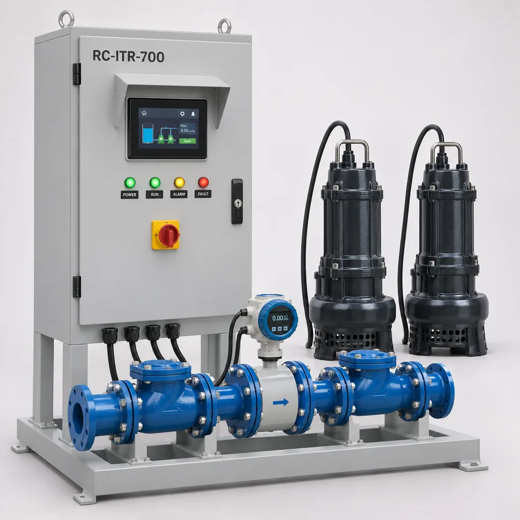
The RC-ITR-700 Smart Irrigation Tailwater Recovery & Runoff Reuse Station is a mains-powered system that collects operating data from an irrigation runoff basin and controls the return of suitable water to an irrigation reservoir. It serves farms, irrigation districts, commercial nurseries and managed landscapes with existing electrical infrastructure, combining pumping coordination, water-quality permissives, metering, a Web platform and a mobile App. Recoverable runoff can carry sediment, nutrients and agricultural chemicals, making controlled collection and reuse a practical water-management requirement rather than simply another pump-starting task; this application is described in UC IPM irrigation recirculation guidance, updated September 2025. REDCOAST.LTD delivers the complete control solution with project-specific PCB and board-level hardware development, while pumps, civil storage and any required treatment are selected for the actual site.
Key Features
- Tailwater-specific operating sequence: coordinates source-basin level, receiving-reservoir capacity, reuse authorization and measured water conditions before allowing a transfer.
- Duty/standby pumping: the reference package uses two 3 kW pumps, with one operating at a time and automatic alternation to distribute running hours.
- Measured recovery volume: a full-pipe electromagnetic flowmeter records transferred cubic metres, instantaneous flow and daily totals for operational water accounting.
- Water-quality permissives: conductivity and turbidity limits can hold transfer when runoff falls outside the operator-approved operating envelope; sensor faults also remove the transfer permission.
- Independent level protection: separate low-level and receiving high-level float switches supplement continuous radar measurements and remain active during local manual operation.
- Custom hardware at the control core: REDCOAST.LTD develops the isolated analog acquisition, digital-input, relay-interface and edge-controller PCBs around the selected instruments and motor-control equipment.
- Local autonomy with remote visibility: pumping logic remains on site, while the Web platform and App provide trends, alarm acknowledgement, maintenance records and controlled setting changes.
- Clear supply boundaries: the reference package includes controls, instruments, pump coordination and discharge metering; basin excavation, lining, drainage channels and treatment equipment are separately scheduled.
Technical Architecture
The hydraulic arrangement consists of a collection basin with an accessible sediment forebay, a screened pump intake, a duty/standby pump pair, individual non-return valves and a common metered discharge to a receiving irrigation reservoir. The reference duty is 40 m³/h at 12 m total dynamic head, using a DN100 common discharge and pumps with 3 kW motor ratings. These are selection values, not a promise that every pump reaches every flow and head in the configurable range. The transfer stage refills storage; a separate irrigation booster supplies sprinkler or drip pressure when required. Collection storage and any emergency overflow route are designed from the site's inflow hydrograph, usable volume, sediment allowance and permitted water-management arrangements.
The control cabinet contains a REDCOAST.LTD edge controller, isolated 4–20 mA acquisition, digital protection inputs, relay interfaces, a 24 V DC power supply, a local touchscreen and separate motor-control circuits. Sensor signals pass through protected interfaces to the controller; motor power passes through appropriately rated switchgear and variable-frequency drives, not through PCB signal relays. A start requires adequate collection level, available receiving capacity, valid quality measurements, an active reuse permit and a proven discharge path. The controller then ramps the duty pump and checks flow establishment. Low source level, high receiving level, excessive pressure, failed flow proving or loss of a mandatory quality signal stops transfer. A pump-specific fault may initiate standby changeover only while all common permissives remain valid.
Run, hold, fault and maintenance states are timestamped locally with the measurements that caused the transition. Cloud services receive these records for dashboards, daily volume reports and notifications; they do not execute the immediate pumping sequence. Each settings change carries a user identity and revision record, and technicians can retrieve buffered measurements after a communication outage. Conductivity indicates dissolved-ion loading and turbidity indicates optical scattering; neither identifies pesticide residues, pathogens or individual nutrients. Reuse permission therefore combines instrumentation with the site's sampling, treatment and agronomic management plan.
Connectivity & Power
Ethernet is the preferred connection at an existing pump house or farm network. An optional 4G LTE Cat 1 bis modem provides telemetry where wired internet is unavailable; modem bands and carrier approval are selected for the destination network. Two isolated RS-485 ports connect field instruments and compatible drives using Modbus RTU, while Modbus TCP connects local supervisory systems. MQTT over TLS or HTTPS carries data to the REDCOAST.LTD platform. Direct internet exposure of the field Modbus interfaces is unnecessary.
The controls use a dedicated AC 100–240 V, 50/60 Hz auxiliary feed. Pump circuits use a separately selected three-phase supply: typically 380–415 V at 50 Hz or 440–480 V at 60 Hz, with matching motors and drives. A control transformer can provide the auxiliary supply where the installation has no suitable neutral. The controller and reference instruments require approximately 25–60 W; this excludes pumps, valve actuators and cabinet climate equipment. At the reference duty, hydraulic power is approximately 1.31 kW; assuming 55% overall wire-to-water efficiency gives approximately 2.38 kW pump input, illustrating why pump demand must be budgeted separately. This configuration uses grid electricity and includes no photovoltaic equipment. A power outage stops pumping; restart requires renewed local permissive checks.
Protection & Reliability
The reference cabinet has an IP55 enclosure design target, with the completed assembly, cable glands, door-mounted devices and cooling arrangement included in verification. It stands above the site design flood level on a fixed plinth. Hot-dip-galvanized steel receives a compatible pretreatment and smooth matte powder-coated topcoat, typically RAL 7035 light grey to limit solar heating. A shaded installation, separated power and signal wiring, coordinated surge protection, protective bonding and shield termination are included in the installation design.
The standard environmental design range is -10 to +45 °C at the cabinet, with the specified heater fitted for subzero conditions; wetted instruments and pumps require unfrozen water within +2 to +40 °C. Colder climates need drained exposed pipework or separately engineered frost protection. High solar load, coastal salt exposure and persistent sand require an agreed coating, sealing and thermal package. Cabinet anchors and sensor brackets are checked against local wind and structural loads; there is no universal wind-speed rating for every mounting arrangement.
Serviceable terminals, replaceable interface boards, removable probes and accessible pump lifting arrangements support long-term maintenance. Pump seals, probe wipers, intake screens and filters remain wear or cleaning items. Warranty scope, spare-board availability, maintenance intervals and response arrangements are specified in the supply agreement rather than inferred from enclosure ratings.
Application Scenarios
- Surface-irrigated field return: install the station beside the low-end collection basin of a furrow- or border-irrigated field. It returns permitted tailwater to storage and records the recovered volume, helping operators coordinate subsequent irrigation with available water.
- Orchard drainage collection: monitor a drainage sump receiving excess irrigation and rainfall from planted blocks. Conductivity trends and transfer holds help operators avoid returning unsuitable drainage without agronomic review.
- Commercial nursery runoff storage: recover water from outdoor growing beds into a dedicated holding reservoir. The station can deliver water to a separately designed treatment train, with downstream treatment-ready feedback required before onward reuse.
- Turf and sports-ground drainage reuse: transfer collected drainage to an existing non-potable irrigation pond at a site with mains electricity. Reservoir level interlocks prevent unnecessary pumping when storage is full, while metering distinguishes recovered water from separately metered purchased supplies.
- Shared irrigation infrastructure: connect several independently controlled recovery stations to one district dashboard. Operators can compare transfer volumes and maintenance needs while each station retains its own local limits and reuse permissions.
Case-style Examples
The following are illustrative configuration examples, not claims of completed installations or measured customer savings.
Field tailwater return retrofit. An operator already has a collection pond and return pipeline but starts the pump manually. A reference RC-ITR-700 package adds two 3 kW duty/standby pumps, two level instruments, a DN100 flowmeter and conductivity/turbidity permissives. If the accepted pump curve and field measurement establish 40 m³/h, three operating hours transfer 120 m³; this is a volume calculation, not an assumed percentage reduction in farm water use. The operator gains a repeatable start/stop sequence and a traceable transfer record.
Nursery runoff holding and treatment coordination. A nursery wants to reuse collected runoff but must control plant-pathogen risks. The station transfers authorized water into dedicated holding storage and exchanges ready/fault signals with a separately specified filtration and disinfection system. Loss of treatment readiness prevents the relevant onward transfer, and a quality-sensor fault generates a hold rather than an automatic bypass. The operational result is a documented interface between collection, storage and treatment.
Managed-landscape reservoir refill. A sports complex has usable drainage water and an existing irrigation pump house with Ethernet. The station alternates the recovery pumps, stops at the receiving pond's high level and reports recovered volume alongside a separately metered makeup supply. The expected benefit is clearer water accounting and fewer routine pump-start visits; actual savings depend on rainfall, irrigation demand and storage availability.
Customization & Selection Guide
Begin with measured or estimated recoverable inflow, required transfer time, source and destination elevations, pipe length, internal diameter, fittings and water condition. The reference 40 m³/h at 12 m duty must be checked against a pump curve at the selected supply frequency. Select intake screening, solids passage and impeller materials for the debris and abrasion expected after the sediment forebay. Available motor classes span 1.5–7.5 kW per pump; maximum flow and maximum head are not automatically available together.
Instrumentation should match the operating decision. Radar offers non-contact level measurement; commercially documented examples include the VEGAPULS C 21. Electromagnetic metering requires a filled pipe, suitable conductivity and the selected manufacturer's installation conditions; the reference accuracy class is benchmarked against published Promag W 400 specifications. Instrument brands, ranges and certificates are fixed in the project submittal.
Select automatic probe wiping for fouling-prone runoff and retain access for calibration and grab sampling. Establish conductivity and turbidity limits from crop tolerance, soil conditions, treatment capability and the site's approved reuse plan; no single threshold suits every crop. Storage detention may help sediment settle, but it does not establish a universal pesticide breakdown time. If unsuitable inflow continues while transfer is inhibited, the site needs sufficient containment and an agreed upstream irrigation-stop or other permitted management response.
Deployment & After-sales
Delivery starts with a hydraulic schedule, electrical supply details, instrument locations, communications survey and agreed control sequence. REDCOAST.LTD then develops the board interfaces, cabinet drawings, firmware configuration, platform views and commissioning documents as one package. The manufacturing schedule is confirmed after design approval, pump and instrument selection, component availability and any required testing are established; new PCB development adds prototype and verification work.
Factory acceptance includes I/O simulation, pump-fault changeover, sensor-disconnection behavior, quality holds, receiving-reservoir interlocks, communication loss and power-return sequencing. Site acceptance checks pump direction, actual flow and head, meter installation, level calibration, electrical protection, telemetry and operator procedures. Handover includes wiring diagrams, I/O lists, firmware identification, configuration backups, maintenance instructions and user training. Remote diagnostics, replaceable control boards, instrument servicing and integration support are scoped in the service agreement.
Standards & Compliance
The project compliance plan addresses low-voltage switchgear assemblies using IEC 61439-1 together with the applicable requirements of IEC 61439-2:2020. Enclosure protection is assessed using IEC 60529. Turbidity instrumentation can be selected to the appropriate measurement method in ISO 7027-1:2016; measurement-method conformity does not constitute irrigation-water approval.
Electrical safety, EMC, radio approval, material restrictions and any required market markings are determined for the supplied configuration and destination. A component certificate does not certify the complete station, and this product definition makes no claim of completed third-party certification. Water abstraction, reuse, storage and discharge requirements remain site-specific. The NRCS tailwater recovery practice reference provides useful planning context, while explicitly directing designers to applicable local technical guidance; it is not a global product certification.
Why REDCOAST.LTD
REDCOAST.LTD provides an integrated hardware, firmware, Web-platform and mobile-App solution with one coordinated technical scope. Its in-house PCB and board-level design capability allows the signal interfaces, isolation, relay allocation, connectors, enclosure layout and communications to follow the customer's existing pumps and operating rules. Established industrial pumps and calibrated sensing elements are combined with REDCOAST.LTD control electronics, avoiding unsupported claims of manufacturing every component. The reference specifications define a concrete selection starting point; the approved technical submittal fixes the delivered duty, components and acceptance evidence.
Contact REDCOAST.LTD with your runoff volume, required pumping head, water-quality data and electrical supply to specify a custom RC-ITR-700 tailwater recovery solution.
Specifications
Hydraulic Duty & Pump Package
- Reference Transfer Flow
- 40 at the specified reference duty m³/h
- Reference Total Dynamic Head
- 12 at 40 m³/h m
- Reference Pump Motor Ratings
- 2 × 3; motor shaft ratings kW
- Pump Arrangement
- 1 duty + 1 standby; 1 pump operating at a time
- Project Flow Selection Range
- 20–60; pump-curve selection required m³/h
- Project Head Selection Range
- 5–20; maximum flow and head are not simultaneous guarantees m
- Common Discharge Connection
- DN100 reference; DN80 or DN125 alternatives; PN10 flanges
- Pump Solids Passage
- 25–50 by pump selection; upstream screening required mm
Level, Flow & Runoff Instrumentation
- Radar Level Channels
- 2; configured measuring distance 0.2–8 m
- Selected Radar Accuracy Class
- ±5 under sensor reference conditions; installed accuracy verified on site mm
- Electromagnetic Flowmeter Accuracy Class
- ±(0.5% of reading + 1 mm/s velocity equivalent), under manufacturer reference conditions
- Conductivity Measurement Range
- 0.05–20 with temperature compensation mS/cm
- Conductivity Display Resolution
- 0.01 mS/cm
- Turbidity Measurement Range
- 0–1000; infrared optical probe, wiper option FNU
- Discharge Pressure Range
- 0–4 bar
- Independent Float Switches
- 2; source low-low and receiving reservoir high-high
Control Hardware & I/O
- Analog Inputs
- 8 isolated 4–20 mA channels; 16-bit conversion
- Digital Inputs
- 16 optically isolated, 24 V DC
- Relay Outputs
- 12 dry contacts, 2 A at 24 V DC resistive; interface circuits only
- Analog Outputs
- 2 isolated 4–20 mA channels
- Pump Control Channels
- 2 VFD interfaces with run, ready and fault feedback
- Local Logic Cycle
- 100; excludes sensor response and actuator travel ms
- Flow-Proving Timeout Setting
- 10–120 after pump start s
- Quality Alarm Persistence Setting
- 10–600; selected to suit probe response and process risk s
Mains Power & Electrical Loads
- Control Auxiliary Input
- AC 100–240, single-phase, 50/60 Hz V
- Pump Supply Options
- AC 380–415, three-phase, 50 Hz; or AC 440–480, three-phase, 60 Hz; matching motor/drive variant V
- Controller & Reference Instrument Load
- 25–60; excludes motors, valve actuators and climate equipment W
- 24 V DC Power Supply Rating
- 150 total; external loads allocated within remaining capacity W
- Selectable Motor Rating per Pump
- 1.5 / 2.2 / 3 / 4 / 5.5 / 7.5; reference 3 kW
- Reference Installed Motor Capacity
- 6 total; 3 operating motor shaft rating in duty/standby mode kW
- Cabinet Anti-condensation Heater
- 100; thermostatic, fitted for subzero cabinet operation W
Communications & Data
- Ethernet
- 1 × 10/100BASE-T
- Cellular Option
- 4G LTE Cat 1 bis; destination-specific band variant
- Serial Field Interfaces
- 2 isolated RS-485 ports; 9.6–115.2 kbit/s
- Integration Protocols
- Modbus RTU, Modbus TCP, MQTT over TLS 1.2+, HTTPS
- Local Storage Capacity
- 200000 timestamped multichannel records; approximately 138 days at one record per minute records
- Periodic Logging Interval
- 1–60; separate event-triggered records min
- Cloud Reporting Interval
- 1–15 plus event messages when connected min
Enclosure & Environment
- Cabinet Ingress Protection Target
- IP55 for completed assembly; project verification required
- Cabinet Ambient Design Range
- -10 to +45; heater below 0, shaded installation °C
- Reference Wetted Operating Range
- +2 to +40; unfrozen water °C
- Reference Cabinet Dimensions
- 1200 × 800 × 400, H × W × D; excludes plinth mm
- Cabinet Finish
- Hot-dip-galvanized steel with compatible pretreatment and smooth matte powder coating, RAL 7035
- Control PCB Protection
- Conformal coating on exposed circuitry; service connectors masked
- Relative Humidity
- 5–95, non-condensing inside cabinet %
Operator Interface & Software
- Local Touchscreen
- 7-inch, 800 × 480 pixels; IP55-compatible installed front
- Operating States
- Automatic, local manual, quality hold, fault, maintenance
- Access Roles
- 3 default roles: viewer, operator, administrator
- Volume Registers
- Instantaneous flow, daily total, cumulative total, transfer-batch total
- Alarm Delivery
- Local HMI, Web dashboard, mobile App; email through configured service
- Report Exports
- CSV data export and PDF operating reports
Capabilities — configurable per project
Specifications are tailored to each project — the options below show what we can support.
Supply Scope
- Control-and-instrument retrofit for existing pumps
- Complete duty/standby pump and metering package
- Recovery package with separately specified treatment interlocks
Runoff Instrumentation
- Level, flow and pressure
- Level, flow, pressure, conductivity and turbidity
- Expanded package with pH and automatic sampling interface
Backhaul
- Ethernet
- 4G LTE Cat 1 bis
- Ethernet with 4G fallback
Environmental Package
- Standard shaded outdoor cabinet
- Coastal coating and sealed heat-exchanger package
- Cold-climate cabinet and engineered pipe frost protection
Platform Deployment
- REDCOAST.LTD hosted Web platform and App
- Private server deployment
- Existing SCADA integration through documented Modbus registers
Related solution guidance
Environmental Monitoring
Deploy environmental monitoring stations with sensors, solar power, gateways, dashboards, alarms and data integration for city and industrial sites.
Power and Connectivity
How to choose power, battery, solar, NB-IoT, LTE, LoRaWAN, gateways and monitoring strategy for outdoor IoT infrastructure.
Ports and Logistics
Outdoor IoT infrastructure for ports, yards and logistics areas: lighting, guidance, safety, solar power, monitoring and maintenance visibility.
Frequently Asked Questions
What does an irrigation tailwater recovery station do?
It controls the transfer of collected irrigation runoff from a basin to a reservoir or another approved reuse point. The RC-ITR-700 checks levels, flow and configured water-quality permissives, then records the volume transferred. Collection drains, basin capacity and any treatment must be designed as part of the overall site system.
How is this different from an irrigation booster pump station?
A tailwater station recovers runoff and normally transfers it into storage at a relatively modest head. A booster station supplies the pressure required by the downstream sprinkler or drip network. The RC-ITR-700 reference duty is 40 m³/h at 12 m total dynamic head; it does not imply adequate pressure for every irrigation distribution system.
Does the station remove pesticides, salts or plant pathogens?
No: the reference package monitors and transfers water; it does not provide chemical removal or disinfection. Conductivity and turbidity can trigger operating holds, but they cannot establish pesticide or pathogen safety. Sampling, agronomic limits and any filtration, disinfection or other treatment must be specified for the water and intended reuse.
What electricity supply is required, and are solar panels included?
The reference controls require AC 100–240 V at 50/60 Hz, while the pumps require a separately matched three-phase supply. Typical pump variants use 380–415 V at 50 Hz or 440–480 V at 60 Hz. This product configuration is intended for electrically serviced sites and includes no solar panels.
Can it reuse our existing pumps, reservoir and irrigation software?
Yes, after checking pump curves, motor ratings, protection circuits, available storage and instrument installation conditions. REDCOAST.LTD can supply a control-and-instrument retrofit using existing compatible drives and connect to supervisory software through documented Modbus interfaces. Reservoir repairs, hydraulic changes and third-party integration work are identified in the project scope.
What happens if the internet fails or runoff quality becomes unsuitable?
Internet loss leaves the local control sequence active and measurements buffered, although remote notifications are delayed. A failed mandatory quality sensor or an exceeded operating limit holds transfer until the configured recovery conditions are met. The site must provide containment and an agreed response to continuing inflow; stopping a pump alone cannot prevent a basin from overflowing.
How much water can this system save?
The station meters actual recovered volume rather than promising a fixed percentage saving. At a verified 40 m³/h operating point, three hours of transfer represents 120 m³ moved to storage, before subsequent storage and distribution losses. Net freshwater savings depend on usable runoff, irrigation demand, water suitability, reservoir losses and the existing operating baseline.
Can REDCOAST.LTD develop custom electronics for this station?
Yes. REDCOAST.LTD can design new PCBs and board-level interfaces for the selected sensors, isolation requirements, relay allocation, connectors and communications. Firmware, Web dashboards and the mobile App are developed around the same control sequence, while pumps and calibrated sensing elements are selected from appropriate industrial suppliers.