Overview
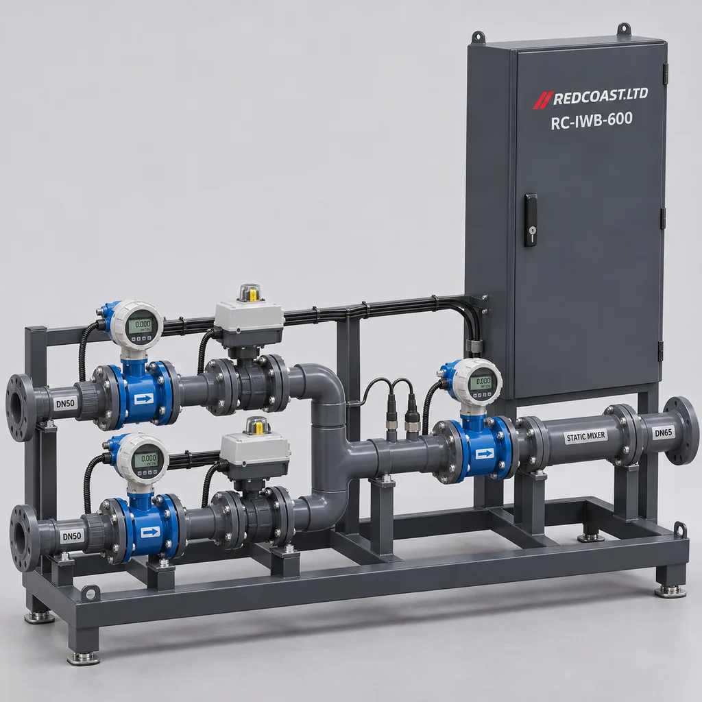
The RC-IWB-600 is a grid-powered irrigation water blending and salinity control station from REDCOAST.LTD for landscaped campuses, public parks, sports facilities, and commercial nurseries with two available water sources. It combines a metered hydraulic skid, local control cabinet, Web management platform, and mobile app to regulate how much lower-conductivity and higher-conductivity water enters the irrigation supply. Operators gain repeatable blending recipes, source-volume records, and automatic shutdown when the agreed operating conditions cannot be maintained. This configured-to-order product addresses water-source management upstream of irrigation scheduling and fertilizer injection; the specifications below define a proposed engineering configuration and acceptance targets, with final ratings fixed in the project datasheet.
Key Features
- Three-point conductivity measurement: Monitor both incoming sources and the mixed outlet using temperature-compensated EC measurements, so changes in source quality are visible before operators adjust a recipe.
- Measured source allocation: Three electromagnetic flowmeters record each inlet and the common outlet, providing source totals and a flow-balance diagnostic with configurable delay and tolerance.
- Closed-loop blending: Independent modulating valves combine a calculated starting ratio with outlet EC feedback, reducing dependence on manually adjusted valves.
- Local operating continuity: Approved recipes, permissive checks, and alarms execute locally when the Internet connection is unavailable; remote access enhances supervision without carrying the control loop.
- Defined fault response: Low source level, insufficient pressure, invalid conductivity, valve-position faults, and sustained outlet EC excursions withdraw the irrigation permissive and initiate a controlled stop.
- Practical plant integration: Pump-run permissions, treatment-ready inputs, an irrigation-demand contact, and Modbus interfaces connect the skid to existing pumping, treatment, and landscape-control equipment.
- Traceable water management: The platform records requested and measured EC, source fractions, delivered volume, alarm acknowledgments, and operator changes for maintenance and resource reporting.
- Project-specific electronics: REDCOAST.LTD develops the conductivity acquisition, isolated field-interface, valve-control, and supervisory controller PCBs to match the selected instruments and operating sequence.
Technical Architecture
The base skid has two DN50 pressurized inlets and one DN65 outlet. Each inlet includes service isolation, a check valve, an electromagnetic flowmeter, an EC/temperature probe, a pressure transmitter, and a modulating valve with spring-return closure. The streams join upstream of a static mixer; a third EC probe and flowmeter measure the blended water before delivery. Sample and drain points support calibration and winterization. Both supplies enter as non-potable process water: any drinking-water top-up must first pass through a separately engineered break tank and suitable air gap. Feed pumps, upstream treatment, and the downstream irrigation distribution system are separate equipment with defined control interfaces.
The controller initially estimates the higher-EC source fraction as (EC_target - EC_A) / (EC_B - EC_A), using measurements referenced to 25°C and only when source B has a sufficiently higher EC than source A. This is a starting approximation, because conductivity is affected by ionic composition and is not an exact mass-concentration measurement. Flow feedback establishes the requested ratio, while the outlet EC loop trims it after allowing for pipe transport, mixing, sensor response, and actuator travel. A setpoint outside the achievable source range generates an unavailable-recipe alarm; nearly equal source readings disable the ratio calculation. Commercial process-water blending also uses flow and conductivity feedback, as illustrated by Bürkert's blending-system reference.
The REDCOAST.LTD acquisition PCB provides alternating excitation and temperature inputs for compatible conductivity cells, with isolated interfaces separating field signals from the controller. A dedicated I/O board reads pressure, flow, tank-level contacts, and actuator feedback; the supervisory board manages recipes, timestamps, local storage, and authenticated communication. Startup water must pass through a commissioned return or diversion route until outlet quality is qualified, or enter a designated non-potable buffer tank while irrigation delivery remains disabled. If no suitable startup route exists, automatic direct-to-network startup is not enabled. The Web platform and app display trends and maintenance tasks, while local logic retains authority over permissives and shutdown.
Connectivity & Power
The station operates from AC 100–240 V, 50/60 Hz, at an existing pump house, utility compound, or landscaped-site service point. An isolated 24 V DC supply powers instruments, controls, and actuators. The base electrical budget is 40–90 W during normal operation and 180 W maximum, excluding source pumps, external diversion equipment, pipe heating, and building ventilation. The published configuration contains no photovoltaic array or battery.
Ethernet is the standard uplink for managed sites; optional 4G LTE provides access where a network cable is impractical, with the modem variant selected for local bands and operator approval. Two isolated RS-485 ports and Modbus TCP support field and supervisory integration. MQTT over TLS and HTTPS carry telemetry and configuration through an approved network path. Remote commands require authorized accounts and remain subject to local interlocks; buffered records upload after connectivity returns. Mains failure removes pump and irrigation permissions, and mechanical spring-return actuators close the source valves without cloud access.
Protection & Reliability
The control cabinet has an IP65 design target with sealed cable entries, segregated mains wiring, protective earthing, and surge protection coordinated with the site electrical system. The base wet skid is specified for ambient temperatures of +5 to +45°C and water temperatures of +5 to +40°C. Operation outside that envelope requires a separately sized shelter, ventilation, insulation, or trace-heating package; an electronics component temperature rating does not establish the temperature rating of the assembled skid.
The steel frame and cabinet use hot-dip galvanizing beneath a smooth matte powder-coated finish. Coastal exposure calls for a specified coating system, compatible fasteners, and a maintenance plan; no salt-spray duration or corrosion lifetime is claimed without the selected assembly's test evidence. PVC-U manifolds, EPDM seals, and compatible probe materials are checked against actual water chemistry, including cleaning agents. Outdoor installations require sun protection for exposed polymer pipework and anchors designed for the site's wind and structural conditions.
Valve closure timing must be coordinated with pump stopping and transient-pressure analysis. Fault detection cannot remove water already between the outlet sensor and the irrigation emitters, so the selected buffer or diversion arrangement determines containment performance. Replaceable probes, accessible strainers, manual sampling points, and pluggable controller modules support maintenance. Warranty duration, spare-parts provision, and service response are defined in the supply agreement rather than inferred from component ratings.
Application Scenarios
- Campus landscape water-source management: Install the station in a grid-connected irrigation service compound receiving treated reclaimed water and a lower-EC supply from an isolated storage tank. Facilities teams can apply approved blending recipes and review how much of each source supplied individual irrigation periods.
- Public parks with borehole and stored rainwater: Place the skid between the source pumps and the irrigation header. Measured source EC helps the controller adjust proportions as borehole conductivity changes or stored rainwater becomes scarce.
- Sports turf and golf practice facilities: Use centrally approved water-quality recipes for turf areas with different agronomic requirements. Operators can review delivered EC alongside soil testing and drainage observations rather than treating one water-quality reading as proof of turf health.
- Commercial nurseries and landscape plant production: Stabilize incoming irrigation-water EC before a separate fertilizer dosing unit. A predictable starting-water condition makes nutrient-recipe management easier, while the nutrient controller retains responsibility for final fertilizer EC and pH.
- Municipal landscape maintenance depots: Feed an existing non-potable irrigation-water buffer tank from two available sources. Tank-level permissions and source totals help operators coordinate filling with irrigation demand and investigate unexpected source consumption.
Case-style Examples
The following are illustrative engineering scenarios, not completed customer installations or measured savings claims.
Campus reclaimed-water blending. A campus has treated reclaimed water at 2.2 mS/cm and an isolated lower-EC supply at 0.4 mS/cm, with a proposed irrigation target of 1.0 mS/cm at 12 m³/h. The starting estimate is 33.3% reclaimed water, approximately 4 m³/h, mixed with 8 m³/h of the lower-EC source. Outlet feedback adjusts that estimate after mixing; the expected operational benefit is a recorded, repeatable source allocation within an agronomist-approved operating window, subject to separate reclaimed-water quality approval.
Nursery borehole-water stabilization. A nursery's borehole EC varies during the season while stored rainwater is available intermittently. The station measures both sources, verifies minimum tank levels, and supplies a buffer tank ahead of the existing fertigation unit. When rainwater is depleted, an unavailable-recipe condition stops blending or invokes an explicitly approved alternative recipe, preventing an unnoticed change in the nutrient system's incoming water.
Sports-ground retrofit with an existing controller. A grounds team retains its irrigation scheduler and pump controls but adds the RC-IWB-600 upstream of the irrigation buffer tank. A demand contact requests blending, and a treatment-ready contact permits the reclaimed-water source. The intended result is clearer separation of scheduling, source-quality control, and pump operation, with source-volume reports available to the maintenance team.
Customization & Selection Guide
Start with simultaneous source-water analyses, minimum and maximum demand, available inlet pressures, outlet pressure requirements, and the hydraulic drawing. EC is useful for salinity control, but sodium adsorption ratio, chloride, boron, alkalinity, microbiological quality, soil drainage, and plant sensitivity require separate assessment. Guidance on irrigation suitability treats these as distinct issues; blending does not remove salt or establish that reused water is hygienically suitable. Oregon State University irrigation-water guidance and FAO water-quality evaluation guidance explain these assessment boundaries.
Select the base skid for a total flow of 5–20 m³/h, with at least 1 m³/h through each active inlet during continuous two-source blending. Consequently, the continuous blend range is approximately 20–80% at 5 m³/h and 5–95% at 20 m³/h; 0% and 100% are separate single-source operating modes. Lower minor-source flows need smaller meter and valve trims or a separately engineered batch arrangement. Neither a DN connection size nor the 2–6 bar service-pressure envelope guarantees the required flow: valve authority, mixer loss, meter installation conditions, and downstream pressure must be checked together.
For tighter outlet supervision, select an additional independent EC transmitter and an external diversion valve with position feedback. Select a pressure-managed feed package when existing source pressures cannot provide stable blending, and a protected wet enclosure where freezing or excessive solar heating is credible. Existing landscape controllers can connect through simple demand/permissive contacts; sites requiring central reporting can select a private server or managed platform deployment. Each quoted option identifies its instruments, wiring, firmware behavior, and acceptance tests.
Deployment & After-sales
Installation begins with a P&ID, source-water review, electrical load schedule, communications plan, and agreed fault-response matrix. The skid mounts on a level, drained concrete pad with service access around meters and valves. The installer provides approved source isolation, upstream filtration nominally rated at 130 µm or finer where required by the selected components, appropriate pipe supports, and a safe return or diversion destination. Drinking-water connections require a risk-appropriate physical separation arrangement; inlet check valves are process components and do not constitute the complete potable-water protection scheme.
Factory acceptance should verify pressure integrity at the approved test pressure, meter scaling, probe calibration, I/O mapping, actuator feedback, and shutdown behavior. Site acceptance then checks actual pressure losses, representative blending points, startup qualification, communication loss, source depletion, and restart after mains failure. The outlet-regulation acceptance target applies after stable flow and mixing have been established, with a planned stabilization window of 120–300 seconds to be confirmed during commissioning.
Delivery scheduling follows approval of the hydraulic design, PCB scope, selected instruments, and test plan. A new PCB layout or additional independent protection channel requires prototype and verification time before production release. Handover includes wiring diagrams, configuration backups, calibration instructions, spare-parts lists, and operator training. Initial maintenance should include weekly visual and strainer checks and monthly comparison of EC readings with a calibrated reference, with intervals adjusted using site fouling and drift records.
Standards & Compliance
The project compliance plan addresses cabinet ingress protection under IEC 60529, electrical measurement/control safety under IEC 61010-1, and EMC under IEC 61326-1:2020. These identify assessment scopes, not certificates already issued for the RC-IWB-600. Final acceptance requires evidence for the supplied assembly and its intended installation. IEC ingress-protection publication record, IEC 61010-1 scope, and IEC 61326-1:2020 scope provide the relevant reference framework.
Where treated wastewater is used, ISO 16075-2:2020 provides guidance on project development, water quality, crops, and exposure barriers; it is not a product certification or an EC-only water-release rule. The ISO catalogue records confirmation of this edition in 2026. ISO 16075-2:2020. Potable-water separation is designed to the locally applicable requirements; EN 1717 and its applicable national adoption may form part of that assessment. BSI's current backflow-protection standard record.
The destination-market conformity plan also determines applicable electrical, radio, restricted-substance, pressure-equipment, and installation requirements. CE marking, RoHS documentation, radio approvals, or other requested evidence must match the delivered configuration. No universal certification, hazardous-area rating, drinking-water approval, or regulatory water-quality compliance is implied by this concept specification.
Why REDCOAST.LTD
REDCOAST.LTD delivers the hydraulic controls, embedded firmware, Web platform, and mobile app as one coordinated irrigation-water management solution. In-house PCB and board-level hardware design allows the team to change sensor excitation, input protection, isolation, valve interfaces, and communications around the customer's actual equipment. That flexibility is useful when retrofitting a pump house whose wiring, instruments, or operating sequence do not fit an off-the-shelf controller.
Project delivery connects those hardware decisions to readable operating screens, documented interfaces, testable fault behavior, and service instructions. Buyers can request a defined skid configuration or a site-specific arrangement while retaining an agreed specification and acceptance process.
Contact REDCOAST.LTD with your source-water analyses, required flow, inlet and outlet pressures, and site layout to request a customized RC-IWB-600 blending-station proposal.
Specifications
Hydraulic Configuration
- Process connections
- 2 × DN50 inlets; 1 × DN65 blended outlet
- Total operating flow
- 5–20; subject to inlet head and downstream pressure m³/h
- Minimum active inlet flow
- 1.0 per source during continuous two-source blending m³/h
- Service pressure envelope
- 2–6 at 5–40°C; hydraulic sizing required bar
- Manifold design pressure class
- PN10 at 20°C; assembled service limit 6 bar
- Process water temperature
- +5 to +40 °C
- Upstream filtration basis
- 130 nominal or finer as required; upstream filter separate µm
- Wetted material basis
- PVC-U manifolds, EPDM seals, PVDF/titanium EC probes; chemistry review required
Measurement
- EC measurement points
- 3: source A, source B, blended outlet
- EC measurement range
- 0.10–10.00, referenced to 25°C mS/cm
- EC measurement acceptance target
- ±(2% of reading + 0.02 mS/cm), at 25°C after calibration
- Temperature compensation
- Pt1000; reference 25°C; coefficient adjustable 0–3 %/°C
- Flow measurement points
- 3 full-bore electromagnetic meters; fully flooded pipes
- Flow measurement acceptance target
- ±(0.5% of reading + 0.02 m³/h), clean water, 1–20 m³/h per inlet and 5–20 m³/h outlet
- Pressure transmitters
- 3 × 0–10 bar; selected accuracy ±0.5% full scale
Blending & Local Control
- Source control valves
- 2 × DN50 modulating valves, 24 V DC spring-return closed, position feedback
- EC setpoint range
- 0.30–5.00; limited by measured source EC and approved recipe mS/cm
- Continuous blend fraction
- 20–80% at 5 m³/h; 5–95% at 20 m³/h; each source ≥1 m³/h
- Single-source modes
- 0% or 100% source B, only with approved quality permissives
- Supervisory scan interval
- 1; physical loop response depends on hydraulics and actuators s
- Outlet regulation acceptance target
- ±0.10 mS/cm or ±5% of setpoint, whichever is greater, at commissioned steady conditions
- Planned stabilization window
- 120–300 after stable inflow; confirmed during site commissioning s
- EC excursion persistence setting
- 5–60; critical source-loss and invalid-sensor faults stop without this delay s
Grid Power
- Input voltage
- AC 100–240, single phase V
- Input frequency
- 50/60 Hz
- Normal operating power budget
- 40–90, base controls and instruments W
- Maximum base power budget
- 180; excludes feed pumps, external diversion equipment, and heating W
- Internal DC power supply
- 24 V DC / 10 A rated
- Field actuator supply
- 24 V DC, individually fused branches
Field Interfaces & Connectivity
- Dedicated conductivity interfaces
- 3 EC cell inputs with 3 Pt1000 temperature inputs
- General analog inputs
- 8 × isolated 4–20 mA
- Digital inputs
- 12 × 24 V DC; 3 channels configurable for flow pulses
- Analog outputs
- 4 × 4–20 mA for valve and external pump references
- Relay outputs
- 6 dry contacts, 24 V DC / 1 A resistive; external interposing devices for larger loads
- Wired network interfaces
- 1 × 10/100 Ethernet; 2 × isolated RS-485
- Optional cellular uplink
- 4G LTE Cat 1; modem bands and approvals selected for destination network
- Integration protocols
- Modbus RTU, Modbus TCP, MQTT over TLS 1.2 or later, HTTPS
Operator Interface & Data
- Local display
- 7-inch, 1024 × 600 touchscreen inside the cabinet
- Stored operating recipes
- 16 with source limits, target EC, and fault settings
- Local telemetry retention
- 30 days at 1-minute aggregates for 32 channels
- Telemetry upload interval
- 15–900, configurable s
- User roles
- 4: viewer, operator, maintenance, administrator
- Operator applications
- Web dashboard; Android and iOS mobile app
- Export formats
- CSV time series and event logs; JSON API records
Enclosure & Installation
- Cabinet ingress design target
- IP65 under IEC 60529; final assembly verification required
- Base wet-skid ambient temperature
- +5 to +45; external climate package required outside this range °C
- Ambient humidity
- 10–95, non-condensing % RH
- Frame and cabinet finish
- Hot-dip galvanized steel with smooth matte powder coating, RAL 7016
- Nominal skid envelope
- 2200 × 1000 × 1700, length × width × height; final general arrangement controls mm
- Estimated dry mass
- 180–260, depending on selected valves and meters kg
- Mounting and access
- Anchored concrete pad; nominal 800 mm service clearance at cabinet and instrument side
Capabilities — configurable per project
Specifications are tailored to each project — the options below show what we can support.
Blending supervision
- Three EC probes with outlet feedback
- Four EC probes with an independent outlet transmitter
- Independent outlet verification plus external diversion-valve control
Hydraulic integration
- Pressurized inline skid with a commissioned startup return
- Existing non-potable buffer-tank filling
- Retrofit controls for a surveyed two-source manifold
Connectivity and hosting
- Ethernet with customer-hosted platform
- Ethernet with managed Web platform and app
- 4G LTE with managed Web platform and app
Environmental package
- Shaded pump-house installation
- Outdoor sunshade and enhanced corrosion coating
- Insulated wet enclosure with project-sized heating and drainage
Site control interface
- Dry-contact demand and irrigation permissive
- Modbus integration with the existing irrigation controller
- Pump VFD references and tank-level permissives
- Upstream treatment-ready and external diversion feedback
Related solution guidance

Environmental Monitoring
Deploy environmental monitoring stations with sensors, solar power, gateways, dashboards, alarms and data integration for city and industrial sites.

Street Lighting Guide
A practical guide to choosing smart street lighting controllers, connectivity, platform features, dimming logic and acceptance tests.
Solar IoT Guide
A design guide for solar-powered outdoor IoT: load calculation, battery autonomy, low-power firmware, telemetry and maintenance planning.
Frequently Asked Questions
What does an irrigation water blending station do?
It mixes two available water sources in controlled proportions and measures the conductivity of the resulting irrigation supply. The RC-IWB-600 adds source flowmeters, modulating valves, local control, and remote reporting. Irrigation scheduling and fertilizer dosing remain separate functions connected through defined interfaces.
Can the RC-IWB-600 reduce the salinity of borehole or reclaimed water?
It can lower the mixed-water EC when enough suitable lower-EC water is available. It does not remove dissolved salts, and a target below both source readings cannot be achieved by blending alone. The starting ratio is an estimate that outlet measurement must verify, while sodium, chloride, boron, and plant-specific suitability require separate assessment.
Does a satisfactory EC reading mean reclaimed water is safe for irrigation?
No: EC indicates electrical conductivity and cannot verify pathogen removal or identify all hazardous constituents. Reclaimed water requires its own treatment, sampling, and approval for the intended exposure and use. The station can accept a treatment-ready input, but that input is not an independent water-quality test; project development should consider [ISO 16075-2](https://www.iso.org/standard/73483.html).
What flow rates and blending ratios does the base station handle?
The proposed base configuration covers 5–20 m³/h total flow, subject to a hydraulic assessment. Continuous blending requires at least 1 m³/h from each active source, giving approximately 20–80% at 5 m³/h and 5–95% at 20 m³/h. Single-source operation is a separate approved mode; very small minor-source fractions need different meter and valve sizing or batch blending.
What happens if Internet access or mains power fails?
An Internet outage leaves approved local recipes and interlocks operating, with records buffered for later upload. A mains outage removes the pump and irrigation permissives and causes the spring-return inlet valves to close. The base package has no battery, so ongoing monitoring during a power outage would require a separately specified site power solution. Valve travel, pump stopping, and pipeline surge behavior must be coordinated during engineering.
Can drinking-water mains connect directly to one blending inlet?
The proposed arrangement feeds the blending skid from non-potable process supplies and uses a separate break tank with a risk-appropriate air gap wherever drinking-water top-up is needed. Inlet check valves are not the complete protection arrangement. The final design must follow the local water authority's requirements; [Water Regs UK backflow guidance](https://www.waterregsuk.co.uk/topics/different-types-of-backflow-prevention/) illustrates how protection depends on contamination risk and operating conditions.
Can REDCOAST.LTD adapt the controller to existing pumps and irrigation software?
Yes: the project can define dry-contact handshakes, Modbus data, pump references, and API integration around the surveyed equipment. REDCOAST.LTD develops custom PCBs and embedded firmware as well as the Web platform and mobile app, allowing electrical interfaces and operating logic to change together. Buyers should provide the P&ID, instrument list, pump-control details, network requirements, and source-water analyses.
Are the published figures certified performance results?
They describe the proposed RC-IWB-600 configuration, component-selection requirements, and project acceptance targets. The exact assembly requires hydraulic verification, calibration, functional acceptance, and applicable conformity evidence before its final ratings are released. IP65, regulation accuracy, and environmental limits should be written into the supply specification with the required test evidence.