Overview
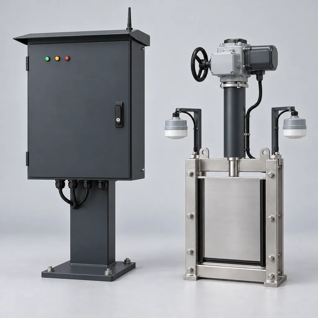
The RC-SDC-600 is a mains-powered smart stormwater detention control station from REDCOAST.LTD for municipal drainage departments, campus operators, industrial estates and infrastructure integrators. It combines upstream and downstream water-level measurement, an electrically actuated outlet gate, local control, a Web management platform and a mobile App to regulate releases from existing detention ponds or underground attenuation tanks. Operators gain visibility of remaining storage, gate position and downstream constraints, with controlled drawdown based on an approved hydraulic operating plan. This product is specified for locations with an electricity supply; the figures below describe a proposed configuration for project quotation, with final ratings established through detailed design and acceptance testing.
Key Features
- Active outlet regulation: Control one gate as standard or two with the expanded I/O assembly, using measured water levels and commissioned discharge limits.
- Upstream and downstream awareness: Two non-contact radar sensors distinguish rising basin levels from downstream surcharge, helping avoid release decisions based on incomplete information.
- Local operation during communication outages: The edge controller retains the approved rule set, sensor checks and actuator limits while the Web connection is unavailable.
- Forecast-assisted scheduling: An optional weather-data interface proposes advance drawdown within locally enforced discharge and level limits.
- Purpose-designed electronics: REDCOAST.LTD develops the isolated sensor-acquisition PCB, supervisory controller, actuator-interface board and monitored low-voltage power-distribution PCB.
- Practical mechanical feedback: Gate-position feedback, independent end switches, torque trips and motor protection identify stalled or incomplete movements.
- Operational records: Time-stamped measurements, command histories, alarm acknowledgments and operator identities support maintenance and event review.
- Integrated delivery: The cabinet, field instruments, actuator interface, firmware, Web platform and App are configured against one project point list.
Technical Architecture
The reference package contains a lockable outdoor cabinet, two 80 GHz-class radar level sensors, one independent upstream high-level float switch and one motorized slide gate. The standard gate opening is 400 × 400 mm, with 200 × 200, 300 × 300 and 600 × 600 mm alternatives. Wetted gate components use 316L stainless steel, EPDM seals and polymer guides; the motor and gearbox remain above the design flood elevation. Seating head, reverse head, stem thrust, debris conditions and anchor loads determine the final mechanical selection. Commercial feasibility is supported by the ORBINOX MU specification, revision June 2024, which documents electrically actuated stainless-steel penstocks across a wider size range; those third-party ratings are not assigned automatically to this package.
The acquisition board reads isolated 4–20 mA inputs, RS-485 instruments and digital contacts. A deterministic controller validates sensor freshness and plausible changes, calculates available storage from the surveyed level-volume curve, and requests a gate position through the actuator's local controls. Mechanical limit switches, torque protection and motor thermal protection remain effective independently of cloud commands. The normal control evaluation interval is 5 seconds, while the minimum interval between movement requests is configurable from 60 to 900 seconds; a duty limiter also enforces the selected actuator's starts and thermal limits. Positioning resolution is not discharge accuracy: reported flow is an estimate derived from a commissioned relationship between gate opening and upstream/downstream head, unless an independent flow instrument is installed.
Normal operation follows a project-specific state table covering detention, permitted drawdown, downstream surcharge, high basin level, sensor disagreement and maintenance lockout. High basin level and downstream surcharge can occur together, so the hydraulic designer must define their priority instead of assuming that opening or closing is always safe. Remote setpoints carry an expiry time and cannot override the local operating envelope. The platform aggregates trends, forecasts and events; the edge controller checks every request against current field conditions. This monitoring-to-control structure follows the established real-time control category described in the EPA smart sewer technology overview.
Connectivity & Power
Ethernet is the first choice where a drainage building, campus network or nearby utility cabinet provides a managed connection. An optional LTE Cat 1 or Cat 4 modem provides telemetry where cable installation is impractical, with frequency bands and network approval selected for the installation country. Fiber can connect through an external media converter when long distances or electrical isolation justify it. RS-485 Modbus RTU connects local instruments, while Modbus TCP is available on a segregated site network; MQTT over TLS and HTTPS serve the platform connection. Internet connectivity supports supervision, reporting and optional forecast access, while the commissioned local control loop remains at the site.
The control cabinet accepts AC 100–240 V, 50/60 Hz, and supplies a nominal 24 V DC field bus from a 120 W power supply. The reference electronics and two level sensors have a 15–25 W operating budget, rising to a maximum design budget of 100 W with the 50 W cabinet heater active. Gate motors use a separately protected, supply-matched 110–120 V or 220–240 V single-phase circuit; nominal motor sizes span 0.18–0.75 kW and are excluded from the cabinet electronics budget. Motor starting current, supply voltage drop and protection coordination are checked separately. On mains loss, the specified self-locking actuator stops and retains its position; restart waits for valid measurements. Any requirement for continued powered movement during an outage requires a separately engineered facility-backed supply.
Protection & Reliability
The cabinet design target is IP66 with its doors closed and correctly fitted glands; radar heads are specified at IP67 or better, and the selected actuator must have at least IP67 protection. These are component-specific requirements, not a declaration that the installed station can operate submerged. The cabinet and motor are placed above the project flood level with the required civil freeboard. The reference enclosure is hot-dip galvanized steel with a smooth matte RAL 7016 powder-coated topcoat and an external sun shield.
The initial ambient design range is -20 to +50 °C, subject to complete-assembly thermal verification at the site's solar exposure. A controlled heater manages condensation; it does not thaw a frozen gate or guarantee level measurement through ice. Coastal installations require a coating system and fasteners selected for the actual chloride exposure, while dusty locations need inspection of glands, seals and actuator breathers. Cabinet supports and sensor brackets are checked for local wind and anchor loads.
Reliable operation depends on accessible maintenance. Debris screens, gate seats and sensing paths require inspection before the wet season and after major storm events. Replaceable terminal modules, surge-protection cartridges, power supplies and controller boards simplify service, while gate travel and torque trends help identify developing obstruction. Warranty scope, spare-parts provisioning and service response are defined in the supply agreement.
Application Scenarios
- Urban detention pond retrofits: Add controlled discharge to a pond with a suitable existing outlet structure and nearby utility power. Operators can observe storage and release only within the downstream capacity established by the drainage study.
- Underground attenuation tanks at campuses: Install the cabinet at ground level and place the actuated outlet in an accessible service chamber. The system coordinates drawdown around monitored sewer levels and records whether the gate actually completed its movement.
- Industrial estate stormwater basins: Combine runoff storage monitoring with supervised outlet control across paved yards and shared drainage infrastructure. A separate pollution-monitoring system can provide a hold-release interlock, although this station does not independently determine water quality.
- Logistics parks and distribution centers: Manage detention outlets serving large roof and pavement catchments. The platform gives facility teams a common view of rising water, outlet availability and maintenance alarms during heavy rainfall.
- Municipal networks of small storage assets: Connect several locally controlled ponds or tanks to one operator dashboard. Network scheduling can stagger permitted releases, provided a hydraulic model establishes how the assets interact.
Case-style Examples
The following are illustrative engineering configurations, not claims of completed REDCOAST.LTD installations or measured performance.
Existing neighborhood detention pond retrofit. Consider a pond with 3,000 m³ of usable storage, a powered maintenance kiosk and an outlet that needs more operational visibility. A configuration with two radar sensors, a 400 × 400 mm gate, Ethernet and a local high-level input would allow the operator to compare actual storage with an approved release plan. If that plan permits an average discharge of 50 L/s, releasing 1,000 m³ takes approximately 5.6 hours under constant-flow conditions with no inflow; changing head or new runoff extends or alters that result. This example establishes a planning timescale, not a guaranteed gate capacity or flood-prevention claim.
Underground tank serving a business campus. Consider an 800 m³ tank whose receiving sewer periodically surcharges. A 300 × 300 mm gate, upstream/downstream radar measurement and a wired connection to the campus platform would support a hold-and-release schedule based on the sewer's available capacity. The expected operational outcome is a visible, auditable release sequence and quicker identification of a stalled gate; any reduction in surface flooding must be demonstrated by the site's drainage model and subsequent observations.
Coordinated storage across a logistics estate. Three existing basins could each receive a local controller and a gate sized for its own outlet, with Ethernet at two sites and LTE at the third. A central scheduler would propose release windows while each station enforces its own downstream-level and gate-duty constraints. During a communication outage, the affected station would revert to its commissioned local mode, with events uploaded after reconnection.
Customization & Selection Guide
Start with the catchment plan, surveyed elevations, level-volume curve, outlet geometry, maximum seating and reverse heads, permitted discharge envelope and downstream surcharge information. Gate dimensions alone do not establish capacity: available head, submergence, inlet losses and debris conditions matter. Existing gates can be retained where their structural condition, actuator duty and position feedback meet the project requirements. New gates require a mechanical sizing calculation and an accessible means of isolation for maintenance.
Choose local level-based control for a straightforward first deployment. Add forecast-assisted operation when reliable weather data, a validated hydraulic model and an approved prerelease policy are available. Commercial use of forecast-responsive storage is documented in the October 2025 StormCapture brochure; it establishes a market application, not a promised performance gain for this station. A forecast can be wrong, so locally measured levels and discharge constraints retain priority.
The proposed 0.3–10 m working distance and ±5 mm reference-condition sensor accuracy target are conservative relative to available hydrological radar instruments, such as the OTT RLS 500. Installed water-level uncertainty also includes mounting survey error, waves, foam and obstructions. Where discharge evidence matters, add a calibrated flow instrument or verify the gate's hydraulic rating experimentally; do not treat a radar reading as a directly measured flow rate. Procurement should also distinguish positioning duty from frequent modulation, as illustrated by AUMA's SA/SAR duty descriptions.
Deployment & After-sales
Deployment begins with an outlet survey, communications check and an agreed operating-state table. The civil package defines concrete condition, anchor loads, cabinet elevation, cable routes, access protection and an independent passive overflow path. The station regulates an existing hydraulic asset; emergency overflow capacity remains part of the civil design. Installation requires a controlled isolation or bypass arrangement where personnel could be exposed to moving water or gate movement.
Factory acceptance covers I/O calibration, actuator interlocks, command limits, sensor-failure responses, communication loss, power restoration and event recording. Site acceptance adds surveyed level checks, full gate travel, manual operation, downstream interlock tests and verification of the discharge relationship. A monitored commissioning period should precede unrestricted automatic operation.
Delivery milestones are agreed after the mechanical survey, approved drawings and component availability review; a standard controller adaptation and a new gate-and-PCB design have different schedules. Handover includes wiring drawings, a point list, controller settings, firmware identification, maintenance instructions and operator training. Remote diagnostics, replacement assemblies and software support are included according to the agreed service scope, with named ownership for civil works, gate maintenance and network administration.
Standards & Compliance
The procurement specification should identify applicable standards and editions for the installation and delivered assembly:
- Enclosure protection: Verify the selected IP targets using IEC 60529, including the completed enclosure's doors, glands and installed accessories.
- Electrical assembly: Where applicable, assess the cabinet against IEC 61439-1:2020 together with IEC 61439-2:2020. Part 1 alone is not an assembly conformity claim.
- Gate and actuator procurement: AWWA C561 for fabricated stainless-steel slide gates and AWWA C542 for electric motor actuators are possible contract references, as listed by the AWWA standards catalog. Their applicability, current editions and project-specific head and leakage requirements must be confirmed.
- Installation acceptance: EMC testing, electrical protection, radio approvals, material declarations and any required market conformity documentation are selected for the complete supplied configuration and installation environment.
Standards references describe the intended assessment route. They do not assert that this newly proposed model already holds third-party certification or completed type-test reports. Discharge consent, stormwater performance and site hydraulic acceptance remain project-specific.
Why REDCOAST.LTD
REDCOAST.LTD delivers the complete outdoor IoT solution: field hardware, control firmware, Web management, mobile App and integration with the customer's operating workflow. Its in-house hardware team can create a new PCB and board-level design for the required channel count, signal isolation, actuator interface, power monitoring and enclosure constraints. Commercial radar instruments and mechanical actuators are selected for their documented capabilities, while the custom electronics and software connect them into an accountable system.
That engineering ownership allows the same product family to accommodate an existing gate, a new outlet assembly, a municipal SCADA point map or a campus maintenance workflow. Procurement can define measurable acceptance criteria and receive one coordinated hardware-and-software deliverable.
Contact REDCOAST.LTD with your basin drawings, outlet dimensions, power supply and discharge requirements to request a tailored RC-SDC-600 configuration and quotation.
Specifications
Hydraulic Assembly
- Controlled Outlets
- 1 standard; 2 with expanded I/O assembly gates
- Clear Gate Opening
- 400 × 400 standard; 200 × 200, 300 × 300 or 600 × 600 alternatives mm
- Differential Head Design Envelope
- 1–3; seating and reverse-head ratings specified separately for the selected gate m water column
- Gate Materials
- 316L stainless-steel frame and slide; EPDM seals; polymer guides
- Nominal Full-Travel Time
- 120–300, selected with gate stroke and gearbox ratio s
- Position Command Range
- 0–100; 1% command increments, not a flow-accuracy rating % open
- Loss-of-Power Behavior
- Self-locking drive retains last position; manual handwheel provided
Level Sensing & Instrumentation
- Standard Level Sensors
- 2 non-contact radar heads: upstream basin and downstream receiving channel
- Radar Frequency
- 77–81, sensor variant subject to local radio requirements GHz
- Configured Working Distance
- 0.3–10, measured from the sensor face to the water surface m
- Sensor Accuracy Target
- ±5 at 20 °C on a stable unobstructed surface; excludes survey and installation errors mm
- Local Measurement Update
- 5 standard; 1–60 selectable with compatible sensors s
- Independent High-Level Detection
- 1 upstream float switch with separate digital input
- Optional Rain Gauge Resolution
- 0.2 per tip; liquid precipitation only mm
Controller & Actuator Interfaces
- Analog Inputs
- 6 isolated 4–20 mA channels; 16-bit conversion
- Digital Inputs
- 12 isolated 24 V DC or dry-contact channels
- Relay Outputs
- 8 dry contacts, rated 2 A at 30 V DC resistive; actuator command circuits only
- Analog Outputs
- 2 isolated 4–20 mA position-command channels
- Instrument Buses
- 2 isolated RS-485 ports, Modbus RTU, 9,600–115,200 bit/s
- Control Evaluation Interval
- 5 s
- Minimum Movement-Request Interval
- 60–900; additional starts and duty limits follow the selected actuator s
- Local Operator Interface
- 4.3-inch display inside cabinet; Local-Off-Remote selector
Mains Power
- Controller Input Voltage
- AC 100–240, single phase V
- Input Frequency
- 50/60 Hz
- Controller and Sensor Operating Budget
- 15–25 typical design budget; 100 maximum with heater; excludes gate motors W
- Field Power Supply
- 24 V DC nominal, 5 A, 120 W rated output
- Actuator Supply Options
- AC 110–120 or 220–240, single phase; separate motor variant and protected circuit V
- Actuator Motor Rating
- 0.18–0.75 per gate; electrical running demand and starting current verified separately kW
- Anti-Condensation Heater
- 50, thermostat/humidity controlled W
Communications & Software
- Wired Network
- 1 × 10/100 Ethernet RJ45; external fiber media-converter option
- Cellular Option
- LTE Cat 1 or LTE Cat 4; country-specific bands and SIM
- Application Protocols
- MQTT over TLS, HTTPS; Modbus TCP on a segregated local network
- Cloud Upload Interval
- 10–300 configurable; alarms sent immediately when connected s
- Local History Capacity
- At least 90 days for 16 channels at 1-minute intervals on 8 GB storage
- Security Design
- TLS 1.2/1.3, unique device identity, role-based access, signed firmware updates
- Operator Deliverables
- Web dashboard, mobile App, alarm acknowledgment, CSV export and REST API
Environmental & Mechanical Design
- Cabinet Protection Target
- IP66 with closed doors and correctly fitted glands; above-flood installation
- Field Equipment Protection
- Radar heads IP67 or better; actuator IP67 minimum; no submerged-operation claim
- Ambient Operating Design Range
- -20 to +50; complete-assembly thermal verification required for site solar exposure °C
- Cabinet Dimensions
- 700 × 500 × 250, excluding pedestal, sun shield and cable entries mm, H × W × D
- Cabinet Construction
- Hot-dip galvanized steel substrate with smooth matte RAL 7016 powder-coated topcoat
- Mounting Arrangements
- Concrete-plinth pedestal or wall bracket; cabinet above the design flood elevation
- Installation Classification
- Non-hazardous location; enclosed electronics maintained non-condensing
Operating Modes & Project Configuration
- Local Operating Modes
- Manual, level-based detention, controlled drawdown, maintenance lockout
- Supervisory Option
- Forecast-assisted scheduling with expiring commands and local constraint enforcement
- Gate Feedback
- 4–20 mA position, open limit, closed limit, torque fault and motor thermal fault
- Communication-Loss Response
- Continue the commissioned local rule set; buffer measurements and events
- Sensor-Fault Response
- Enter the commissioned fault state; inhibit forecast-driven commands
- Hydraulic Model Inputs
- Level-volume curve, gate rating, downstream limits and permitted discharge envelope
- Reference Supply Scope
- 1 cabinet, 2 radar sensors, 1 high-level float, 1 actuated gate, Web platform and App configuration
Capabilities — configurable per project
Specifications are tailored to each project — the options below show what we can support.
Outlet Assembly
- Existing-gate actuator and feedback retrofit
- New 316L wall-mounted slide gate
- Two-gate station with expanded I/O
Control Strategy
- Local level-based detention and drawdown
- Downstream-level-constrained release
- Forecast-assisted scheduling within approved limits
Backhaul
- Managed Ethernet
- LTE Cat 1 or Cat 4
- Fiber Ethernet through an external media converter
Measurement Package
- Upstream and downstream radar pair
- Radar pair plus tipping-bucket rain gauge
- Radar pair plus independent discharge-flow instrument
Platform Delivery
- Hosted Web platform and mobile App
- Customer-hosted server deployment
- Municipal SCADA integration with API and point mapping
Related solution guidance

Environmental Monitoring
Deploy environmental monitoring stations with sensors, solar power, gateways, dashboards, alarms and data integration for city and industrial sites.
Solar IoT Guide
A design guide for solar-powered outdoor IoT: load calculation, battery autonomy, low-power firmware, telemetry and maintenance planning.

Street Lighting Guide
A practical guide to choosing smart street lighting controllers, connectivity, platform features, dimming logic and acceptance tests.
Frequently Asked Questions
What does a smart stormwater detention controller actually control?
It adjusts an outlet gate to manage releases from a detention pond or attenuation tank using measured water levels and an approved operating plan. The RC-SDC-600 combines field sensors, local automation, gate feedback, a Web platform and an App. It does not create additional physical storage; the civil structure and downstream drainage capacity still determine the available operating envelope.
Can the RC-SDC-600 retrofit an existing detention pond or outlet gate?
Yes, the proposed configuration can retain an existing outlet and gate if their condition, head rating, actuator duty and feedback are suitable. A survey establishes mounting dimensions, stem loads, supply availability and the required control interfaces. Where the existing assembly cannot meet those requirements, the package can include a new 200–600 mm square slide gate selected for the actual hydraulic load.
What electricity supply is required, and how much power does the station use?
The control cabinet accepts AC 100–240 V at 50/60 Hz, with a 15–25 W electronics-and-sensor design budget and a 100 W maximum cabinet budget when the heater operates. Gate motors have separately selected 110–120 V or 220–240 V single-phase supplies and nominal ratings of 0.18–0.75 kW per gate. Motor nameplate rating is not the complete electrical consumption figure, and starting current must be included when sizing the feeder.
What happens if internet connectivity or mains power is lost?
During an internet outage, the controller continues its commissioned local rules and buffers records for later upload. During a mains outage, the specified self-locking actuator stops and holds its last position; powered movement resumes only after supply restoration and valid sensor checks. That behavior must be assessed with the passive overflow route and site hydraulics, because no single gate position is safe for every basin. Sites requiring movement throughout an outage need a separately engineered backed facility supply.
Does the station guarantee flood prevention or a fixed percentage reduction in runoff?
No universal flood-reduction percentage is claimed. Outcomes depend on rainfall, available storage, incoming runoff, gate capacity, downstream conditions and the approved control strategy. A hydraulic model and monitored commissioning establish site-specific performance criteria, while passive overflow provision remains part of the civil design.
Does a ±5 mm radar specification mean the discharge flow is equally accurate?
No; the ±5 mm target applies to the selected sensor under the stated reference conditions, before mounting survey error and site effects. Flow inferred from gate position and water levels also depends on the hydraulic rating, debris and downstream submergence. Where discharge measurement is required for reporting or acceptance, include an appropriate calibrated flow instrument or a site-verified hydraulic rating.
Can weather forecasts trigger automatic drawdown before a storm?
An optional forecast interface can request advance drawdown after the site's hydraulic limits and prerelease policy have been approved. The local controller checks downstream level, sensor health, command expiry and actuator limits before moving the gate. Forecast access does not override the local operating envelope, and loss of that service returns the station to its commissioned local mode.
Can REDCOAST.LTD customize the electronics and integrate our existing platform?
Yes; REDCOAST.LTD can develop new PCBs and board-level hardware for the required sensor channels, isolation, actuator interfaces and power monitoring, together with the firmware, Web platform and App. Project integration can use an agreed REST API, MQTT interface or segregated Modbus TCP point map. Provide basin drawings, gate dimensions, seating and reverse heads, discharge limits, available electricity and your SCADA point list to define the quotation.