Overview
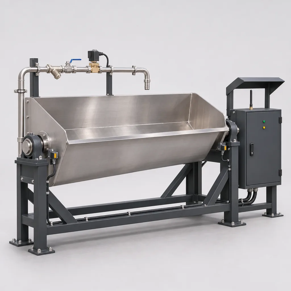
The RC-TFC-600 is a grid-powered stormwater tank flushing system for utilities, municipal drainage operators, infrastructure owners and water-sector integrators. It combines tipping bucket equipment, monitored filling valves, level sensing, local control, a Web management platform and a mobile app to organize cleaning after a storage event. Its purpose is to move suitable settled material toward a designated collection sump while giving operators a record of water use, bucket movement and incomplete cycles. The reference configuration has one 1,000 L stainless-steel bucket with a 2 m effective width, expandable to four sequentially managed lanes. This is a proposed build-to-order specification: hydraulic performance, environmental ratings and delivery scope are finalized through project engineering and configuration-specific validation.
Key Features
- Verified cycle progression: Separate home-position and tip-event inputs distinguish a completed mechanical cycle from a fill command that never produced a flush.
- Measured water consumption: A pulse-output fill-water meter records actual supply volume and helps identify slow filling, unexpected flow and abnormal consumption.
- Local sequence control: Tank level, sump availability, maintenance isolation and supply status determine whether the next filling cycle may begin.
- One to four cleaning lanes: Sequential operation prevents multiple commanded fills and reduces overlapping sediment loads at the collection sump.
- Purpose-built electronics: REDCOAST.LTD develops the sensor-interface, protected valve-output and controller PCBs around the required instruments and installation.
- Utility integration: Ethernet, isolated RS-485 and an optional LTE modem connect the station to SCADA and maintenance workflows.
- Maintenance visibility: The Web platform and mobile app show the last verified tip, aborted cycles, water totals, recurring faults and service records.
- Retrofit delivery: Existing serviceable buckets can receive new instrumentation and controls after a mechanical and electrical interface survey.
Technical Architecture
The equipment package comprises the flushing bucket, engineered supports and bearings, a fill-water assembly, two bucket-position sensors, a tank-level instrument and an above-ground control cabinet. The baseline bucket uses 316L stainless steel and discharges by gravity when its changing center of gravity reaches the mechanical tipping point. A shaped wall-to-floor transition directs the released water into the cleaning lane. This established operating principle is described in Steinhardt's HydroSelf technical information; the RC-TFC-600 adds the proposed monitoring, sequencing and service interface described here. The detailed bucket geometry, tipping threshold, bearing loads and civil supports require their own engineering calculations.
A REDCOAST.LTD controller PCB acquires four 4–20 mA channels, sixteen digital inputs and two pulse inputs. Protected 24 V outputs operate the selected fill valves through appropriately rated interfaces; pump requests pass to the existing motor control center. The state sequence is idle, permissive check, fill, tip detection, return confirmation and drain-down wait. After a recorded tank-use event, the controller requires a stable low tank level, available receiving-sump capacity, a bucket at home and released maintenance isolation before filling. Fill timeout, excessive metered volume, sensor disagreement or lost drainage permission closes the fill valve and latches an identifiable fault. Restart following power loss requires fresh permissive checks and acknowledgment of an interrupted cycle.
The edge controller executes the process without a cloud connection and retains records for later upload. SCADA and the app can request an authorized cycle, but the local sequence evaluates the request before opening a valve. A tip event proves bucket movement; it does not prove that every deposit was removed. Cleaning acceptance therefore uses agreed inspections or other site evidence. Once a gravity bucket has tipped, software cannot stop its discharge, and removing electrical power does not eliminate stored-water or mechanical hazards.
Connectivity & Power
The cabinet takes AC 100–240 V, 50/60 Hz from the site's utility supply and distributes isolated 24 V DC to controls and field devices. The preliminary electrical budget is 25–45 W while monitoring and up to 100 W during filling, excluding the optional 60 W cabinet heater and all external pumps. A 160 W total cabinet allowance covers the stated operating envelope; branch protection and cable sizing must also account for power-supply inrush. Gravity provides the discharge energy, while any equipment used to lift or pressurize the fill water has a separate electrical duty.
Ethernet with Modbus TCP suits treatment works and established facility networks. Two isolated RS-485 ports provide Modbus RTU instrument and legacy-system connections. Optional LTE Cat 1 provides telemetry where wired backhaul is unavailable; modem bands are selected for the installation country. Remote traffic uses an authenticated VPN or TLS-protected service, with Modbus restricted to the facility network. The proposed software provides named accounts, permissions, command logs and expiring remote commands. Loss of backhaul leaves the approved local sequence active and marks remote data as stale.
Protection & Reliability
The outdoor cabinet has an IP66 design target, sealed cable entries, a sunshield and an installation position above the site's assessed flood level. Its steel enclosure and external steel brackets use hot-dip galvanizing beneath a smooth matte powder-coated finish; the wetted bucket remains passivated stainless steel. Salt exposure, wastewater chemistry and cleaning chemicals determine the final metal and coating selection. An IP designation alone does not establish resistance to corrosion, immersion or every cleaning chemical.
The proposed cabinet operating range is -20 to +50 degrees Celsius, with solar heat gain and internal dissipation checked for the installation. Water-filled components operate only under non-freezing conditions; cold-site packages need drained pipework or separately designed insulation and heat tracing. Cabinet heating does not protect remote pipework. Sheltered placement, cable supports and anchors are checked against local wind and structural loads.
A hardware watchdog, output current protection, circuit separation and surge protection support dependable operation. Service planning covers bearings, stops, valve seats, sensor alignment and cabinet seals. Maintenance entry requires physical supply isolation, controlled draining and mechanical restraint under the site's procedures. The standard cabinet is installed outside any classified hazardous area; classified chambers require appropriately approved field devices and a complete installation assessment. Component replacement intervals and warranty terms are documented with the selected operating duty.
Application Scenarios
- Municipal combined-sewer storage tanks: Cleaning can be scheduled after stored flow has been returned to treatment and the tank reaches its cleaning level. The operator receives separate indications for completed, inhibited and failed cycles.
- Urban underground detention tanks: An above-ground cabinet supervises cleaning equipment inside a suitably shaped concrete tank beneath a park or public facility. Logged cycle status helps maintenance teams plan visits without opening every chamber for a routine status check.
- Industrial-campus stormwater basins: Multiple lanes can share a controller where a managed collection route exists for the flushed sediment. Supply metering helps the facilities team allocate cleaning water and investigate changes in filling performance.
- Wastewater equalization tanks: Sequenced flushing supports removal of suitable settled material after drawdown. Process staff approve the receiving capacity and solids loading before each cleaning window.
- Existing tipping bucket installations: New position sensors, metering and controls can replace a timer-only operating arrangement. Reusing mechanically sound equipment reduces replacement scope while adding fault visibility and auditable operation.
Case-style Examples
The following examples illustrate configuration choices and expected workflow; they are not claims of completed customer installations or measured savings.
Municipal storage-tank retrofit. An operator has a serviceable 1,000 L bucket but no reliable record of whether commanded cleaning occurred. An RC-TFC-600 retrofit adds two position sensors, a pulse meter, a tank-level input and Ethernet connectivity to the existing pump station. At a measured net accumulation rate of 60 L/min, theoretical filling takes approximately 16.7 minutes; commissioning establishes the actual tipping threshold and timeout. The intended result is a traceable sequence that separates successful tipping from a blocked supply, position fault or drainage inhibition.
Campus detention facility with four lanes. A new rectangular tank is divided into four engineered cleaning lanes, each with a 1,000 L bucket. One cabinet fills the lanes sequentially and waits for the receiving sump to recover before proceeding. One nominal tip per lane releases 4 m³ of stored flushing water, while metered supply also includes drain and transition losses. Acceptance checks confirm the agreed floor-cleaning result and drainage recovery before unattended operation is enabled.
Customization & Selection Guide
Start with the tank drawings, lane width and length, available drop height, floor slope, surface condition, sediment description and receiving-sump arrangement. Bucket capacity per unit width must be selected with these inputs. Hidrostank's published design guidance describes commercial capacities of 200–2,000 L per meter and the relationship between capacity and tank geometry. The proposed RC-TFC-600 family uses a narrower 250–750 L/m selection range, with widths of 1–4 m; these are dimensional options, not a universal cleaning-distance guarantee.
A pressure-fed filling assembly is the simplest choice when a suitable non-potable supply already exists. Treated effluent or screened recovered water requires compatibility checks for the valve, meter and solids content. Potable backup requires a locally accepted physical separation arrangement, normally an appropriately designed air-gap break tank for this duty, with any transfer pump separately sized. A single check valve is not the proposed protection arrangement.
The receiving system must accept the transient water volume and transported solids. Xylem's stormwater engineering handbook identifies concentrated solids delivery to pumps and treatment as a limitation of flushing methods. Tank geometry, sump storage and downstream acceptance therefore determine the sequence and repeat limit. For wide irregular floors, hardened deposits, insufficient headroom or poor drainage, evaluate another cleaning method before specifying a tipping bucket.
Deployment & After-sales
Delivery begins with a site survey and an agreed package boundary covering mechanical equipment, civil modifications, water supply, controls and software. Retrofit surveys record existing bucket balance, bearing condition, accessible mounting points, valve characteristics and the SCADA register map. New installations require structural verification of the full water mass, bucket mass, tipping forces and anchor arrangement. A filled 1,000 L bucket contains approximately 1,000 kg of water before the equipment's own weight is added.
Factory acceptance should exercise input faults, valve-output behavior, metering, event records and interrupted-cycle recovery. Site acceptance then checks actual fill rate, tip detection, return movement, drainage recovery and cleaning performance using agreed observations. The handover package includes wiring drawings, I/O schedules, approved settings, software access, spare-parts information and maintenance procedures. Procurement planning separates design approval, custom PCB development, fabrication, testing and shipment; a committed schedule follows the approved scope and component availability. REDCOAST.LTD provides remote diagnostics and operator training, with on-site support, warranty duration and spare-parts commitments defined in the project agreement.
Standards & Compliance
The compliance plan is selected for the destination, installation and final equipment scope. The following references describe relevant engineering directions; listing them does not assert existing certification of the proposed model.
- Enclosure protection: Use IEC 60529, including applicable amendments, to verify the final cabinet assembly against the specified IP rating.
- Electrical assembly: Apply IEC 61439-1:2020 together with the relevant assembly part, normally Part 2 for this controlgear scope; Part 1 alone does not establish assembly conformity.
- Mechanical risk assessment: Use ISO 12100:2010 to address moving equipment, stored water, servicing and foreseeable operating conditions. Required safety functions need their own design and validation.
- Electromagnetic compatibility: Where applicable and no dedicated product standard takes precedence, assess industrial immunity against IEC 61000-6-2 and industrial emissions against IEC 61000-6-4. Installations close to residential premises require an environment-specific emissions assessment.
- Water-supply separation: Where adopted, EN 1717:2025+A1:2026 informs backflow risk assessment alongside local water-authority requirements.
The quotation identifies applicable electrical, machinery, radio and substance-restriction obligations, required reports and any destination-specific approvals. Neither a certified component nor an enclosure rating certifies the complete installation. Test evidence and declarations must identify the supplied configuration.
Why REDCOAST.LTD
REDCOAST.LTD develops integrated outdoor IoT solutions spanning equipment, embedded control, a Web platform and a mobile app. For the RC-TFC-600, that includes new PCB layouts and board-level design when the project needs different sensor interfaces, valve loads, isolation, connectors or enclosure packaging. Firmware behavior, field wiring and software records are developed around the same approved operating sequence. This gives utilities and integrators one coordinated delivery scope for site equipment, remote operations and ongoing technical support, while retaining clear interfaces to existing pumps, SCADA and civil infrastructure.
Contact REDCOAST.LTD with your tank drawings, sediment conditions, fill-water supply and control requirements to request a customized RC-TFC-600 configuration.
Specifications
Flushing Hardware
- Reference bucket discharge volume
- 1,000 nominal L
- Reference effective bucket width
- 2.0 m
- Project bucket volume range
- 250–3,000; matched to selected width and capacity per meter L
- Project effective bucket width
- 1.0–4.0 m
- Capacity per meter of effective width
- 250–750; reference configuration 500 L/m
- Controlled cleaning lanes
- 1 standard; 2–4 with additional field equipment lanes
- Bucket wetted material
- 316L stainless steel; welded and passivated
- Discharge mechanism
- Gravity tipping with mechanical return; no tipping motor
Fill Water & Operating Sequence
- Fill-water flow selection
- 30–120 per active lane L/min
- Dynamic supply pressure at fill assembly
- 1–6; selected valve and pipework must meet required flow bar
- Fill connection
- DN32 reference; DN40 option
- Fill valve
- 24 V DC, normally closed; maximum 12 W coil per valve
- Reference theoretical fill duration
- 8.3–33.3 at 120–30 L/min net accumulation; approximately 16.7 at 60 L/min min
- Repeat-flush setting
- 1–3 per lane per event; enabled after site acceptance cycles
- Fill timeout adjustment
- 5–120; commissioned above normal fill duration min
- Lane scheduling
- 1 active fill at a time; next lane waits for sump-recovery permission
Sensing & Custom PCB Interfaces
- Tank-level radar measuring span
- 0.3–10.0; final dead zone follows selected sensor m
- Bucket movement sensing
- 2 proximity sensors per bucket: home and tip event
- Analog acquisition
- 4 isolated 4–20 mA inputs; 16-bit conversion
- Digital inputs
- 16 channels; 24 V DC
- Flow pulse inputs
- 2 channels; 0–100 Hz
- Protected valve outputs
- 6 channels at 24 V DC; 0.5 A per channel, 1.0 A aggregate maximum
- Interposing relay contacts
- 4 outputs; 2 A at 30 V DC resistive; motor loads use external contactors
- Level sensor intrinsic accuracy selection
- ±5 or better under supplier reference conditions; installation uncertainty assessed separately mm
Grid Power
- Input voltage
- AC 100–240 V
- Input frequency
- 50/60 Hz
- Internal DC power supply
- 24 V DC, 5 A rated output
- Monitoring consumption design allowance
- 25–45; controller, display, instruments and communications W
- Active filling consumption design ceiling
- 100; excluding optional heater and external pumps W
- Optional cabinet anti-condensation heater
- 60; thermostatically controlled W
- Combined cabinet operating allowance
- 160 maximum with stated heater; external pumps and pipe heat tracing excluded W
Connectivity & Data
- Ethernet interface
- 1 × 10/100BASE-T
- Serial interfaces
- 2 × isolated RS-485
- Optional cellular backhaul
- LTE Cat 1; country-specific bands and approved modem variant
- Integration protocols
- Modbus TCP, Modbus RTU, MQTT 3.1.1 over TLS, HTTPS API
- Routine upload interval
- 60–900; alarms queued on state change s
- Local trend retention design allocation
- 30 at 60-second sampling for 16 channels days
- Remote-access security
- TLS 1.2/1.3 or authenticated VPN; named accounts and command audit logs
Enclosure & Environment
- Reference cabinet dimensions
- 800 × 600 × 300; height × width × depth mm
- Cabinet ingress protection design target
- IP66; final populated assembly verification required
- Cabinet ambient operating design range
- -20 to +50; sunshield and site thermal assessment required °C
- Unheated fill-water operating range
- +1 to +40; no frozen water or pipework °C
- Cabinet internal relative humidity
- 5–95, non-condensing %
- External cabinet and steel-bracket finish
- Hot-dip galvanized substrate with smooth matte powder coating; RAL 7016
- Cabinet installation classification
- Non-hazardous area, above assessed flood level; classified field devices selected separately
Operator Platform & Service
- Local operator display
- 4.3-inch color HMI behind lockable cabinet door
- Operating selector
- Off / Manual request / Automatic; local permissives apply in both running modes
- Platform hosting
- Managed cloud or customer-hosted server
- User permission levels
- Viewer / Operator / Administrator
- Maintenance records
- Cycle count, last verified tip, fault history, water total and service notes
- Data export
- CSV reports and authenticated HTTPS API
- Operator clients
- Web browser and mobile app
Capabilities — configurable per project
Specifications are tailored to each project — the options below show what we can support.
Delivery Scope
- Complete single-lane equipment and control package
- Two- to four-lane sequential package
- Control and sensing retrofit for an existing bucket
Bucket Geometry
- 1 m width with 250–750 L volume
- 2 m width with 500–1,500 L volume
- 4 m width with 1,000–3,000 L volume
Fill-Water Arrangement
- Pressure-fed non-potable supply
- Screened recovered-water supply with separate transfer pump
- Potable backup through an approved air-gap break-tank arrangement
Communications & Hosting
- Ethernet to existing SCADA
- LTE telemetry with managed Web platform
- Private network with customer-hosted platform
Environmental Package
- Standard coated cabinet with 316L bucket
- Enhanced coastal coating and sealed connectors
- Cold-site drained pipework or engineered trace heating
Related solution guidance
Environmental Monitoring
Deploy environmental monitoring stations with sensors, solar power, gateways, dashboards, alarms and data integration for city and industrial sites.

Street Lighting Guide
A practical guide to choosing smart street lighting controllers, connectivity, platform features, dimming logic and acceptance tests.
Solar IoT Guide
A design guide for solar-powered outdoor IoT: load calculation, battery autonomy, low-power firmware, telemetry and maintenance planning.
Frequently Asked Questions
How does a tipping bucket stormwater tank cleaning system work?
A measured fill-water supply loads an elevated bucket until it reaches its mechanical tipping point, releasing water into an engineered cleaning lane. The RC-TFC-600 supervises filling and confirms bucket movement and return before allowing the next cycle. Effective sediment transport depends on the tank geometry and deposit characteristics, so a tip confirmation is not proof that the floor is clean.
How much water does the RC-TFC-600 use per cleaning cycle?
The reference bucket releases approximately 1,000 L per tip, so four such lanes require 4 m³ of stored water for one tip each. The supply meter records actual water consumption, including drain losses and filling transitions. At a net accumulation rate of 60 L/min, a 1,000 L fill takes approximately 16.7 minutes before tipping and drainage time are added.
Does this system need a high-power cleaning pump or solar panels?
The controller uses AC 100–240 V from the site utility supply, and gravity produces the bucket discharge. The cabinet design allowance is up to 100 W during filling, or 160 W including the stated optional heater; water-transfer pumps and pipe heat tracing are separate loads. Solar equipment is not part of this grid-connected configuration.
Can the controls be added to an existing storm tank tipping bucket?
Yes, a retrofit can retain a mechanically sound bucket while adding position sensing, water metering, local sequencing and remote records. The survey must confirm tipping behavior, support capacity, sensor mounting access, filling equipment and the receiving-sump arrangement. Existing mechanical or civil defects must be resolved before automatic operation is accepted.
Can reclaimed water or potable water be used for filling?
Treated effluent or screened recovered water can be considered after checking solids, chemistry and compatibility with the valve and meter. Potable backup requires a locally approved separation design, typically an appropriate air-gap break-tank arrangement for this application. Its transfer pump, pipework and protection are sized separately from the control cabinet.
What happens if power, communications or a sensor fails?
Loss of communications leaves the approved local sequence available while the platform marks telemetry as stale. Power loss de-energizes the normally closed fill valve, and invalid sensor states inhibit further commanded filling. A bucket already at its tipping point can still discharge, so physical isolation, draining and mechanical restraint remain necessary for maintenance.
How are bucket size and cleaning distance selected?
Selection uses lane width and length, drop height, floor slope, sediment properties and downstream collection capacity. The proposed family spans 250–750 L per meter of bucket width, with widths from 1 to 4 m; these dimensions do not establish a guaranteed cleaning distance. The agreed hydraulic duty and floor-cleaning acceptance criteria are validated for the actual installation.
Does REDCOAST.LTD design the electronics and provide the software?
REDCOAST.LTD develops the controller, sensor-interface and protected valve-output PCBs, including new board layouts for project requirements. The delivery can include embedded firmware, the Web platform, the mobile app and integration with existing SCADA. Configuration-specific compliance evidence, support scope and warranty terms are identified in the approved project documents.