Overview
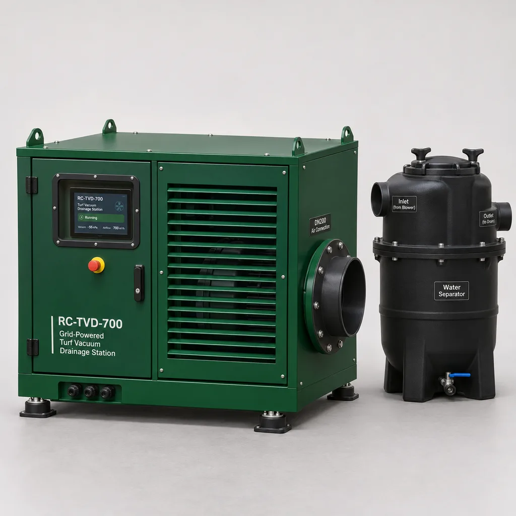
The RC-TVD-700 is an integrated, grid-powered turf vacuum drainage and root-zone aeration system for golf greens, natural-grass sports facilities, and compatible hybrid-grass surfaces. It helps grounds teams manage prolonged root-zone saturation by applying controlled suction to an engineered subsurface drainage network while monitoring soil moisture, temperature, and equipment condition. REDCOAST.LTD combines the blower station, field instrumentation, purpose-designed control electronics, Web platform, and mobile App in one project-configured package. The reference configuration serves one independently isolated drainage zone; larger facilities use multiple stations sized from their drainage layouts and soil conditions.
The specifications below define a reference engineering configuration for quotation and project development. Final airflow, environmental ratings, conformity documentation, and field acceptance criteria are established for the ordered assembly rather than inferred from individual components.
Key Features
- Sensor-informed drainage cycles: Four soil sensing points in the reference package provide moisture and temperature trends; eight points can be configured where different depths or shaded areas need separate observation.
- Controlled subsurface suction: A 5.5 kW motor and variable-frequency drive regulate negative pressure at the drainage connection, with a reference blower selection point of 1,200 m³/h at 2.0 kPa suction.
- Automatic water separation and discharge: A separate collection chamber keeps bulk water away from the blower and coordinates vacuum operation with pressure equalization and gravity drainage.
- Custom control and interface PCBs: REDCOAST.LTD develops the pressure and level acquisition board, protected valve-output circuitry, isolated communication interfaces, and supervisory controller to match the project.
- Local autonomous operation: The station executes commissioned schedules and interlocks locally, including when the internet connection is unavailable.
- Irrigation coordination: An isolated contact or mapped Modbus signal requests an irrigation hold during an authorized drainage cycle, avoiding simultaneous watering and intentional moisture removal.
- Maintenance-oriented diagnostics: Trends for suction, motor current, chamber level, valve feedback, and soil response help distinguish a blocked outlet from an air leak or sensor fault.
- Integrated operator tools: The Web platform and mobile App provide zone maps, alarm acknowledgment, operating history, maintenance records, and controlled remote commands.
Technical Architecture
The station connects to a verified drainage collector through an air-water separation chamber. Its centrifugal blower draws air through the turf profile and drainage pipes, while collected water remains in the chamber. A separate silenced exhaust releases the extracted air above ground. The reference arrangement uses a DN200 air connection and a DN160 or DN200 gravity discharge interface, with final pipe sizes checked against airflow resistance, peak water inflow, and available elevation. This operating principle is established in commercial subsurface aeration and drainage equipment; manufacturer documentation describes the need to separate water and isolate drainage outlets from atmospheric leakage. Sports Pitch Systems technical overview
A REDCOAST.LTD controller reads soil sensors, a differential pressure transmitter, chamber level signals, motor status, and valve position feedback. Before a cycle starts, it confirms the permitted operating window, healthy instruments, available discharge route, and irrigation coordination status. The blower then ramps within its permitted operating curve to the commissioned suction setpoint. Rising water level initiates blower stop, vent opening, verified pressure equalization, and gravity discharge; a new vacuum cycle begins only after the chamber has drained and valve positions have been confirmed. A separate high-high level switch interrupts blower operation independently of cloud software, while a mechanical vacuum relief device limits excessive suction.
The local controller records timestamped measurements and command results before forwarding them to the management platform. Remote requests include an expiry time and pass through the same operating limits as local commands; delayed messages cannot restart a completed cycle. The platform compares soil response with runtime and equipment data, while the App gives authorized maintenance staff access to alarms, service notes, and station status. Site acceptance checks the complete sequence, including communication loss, stuck valves, sensor failure, and interrupted power.
Connectivity & Power
This product is intended for permanently serviced sports and landscape facilities. The reference electrical supply is three-phase AC 380–415 V at 50 Hz, with a separately configured AC 460–480 V, 60 Hz build for compatible sites. Motor, drive, transformer or power supply, protection, and terminal ratings are selected together for the ordered supply. The 5.5 kW motor rating describes mechanical output; a 7.5 kW connected-load allowance covers the reference station's electrical input and auxiliaries. Any separate drainage pump requires its own hydraulic design and electrical allowance.
Ethernet is the preferred uplink where the maintenance building or field equipment network already provides cabling. An optional 4G LTE router serves sites without a practical wired connection, using an externally mounted antenna and an appropriate local operator plan. Isolated RS-485 links connect field equipment, while SDI-12 interfaces accommodate compatible soil probes. MQTT over TLS carries platform telemetry, and documented Modbus mappings support integration with irrigation or facilities systems.
The controller remains responsible for operational interlocks during network outages and buffers records for later upload. Loss of mains power stops the blower and releases the spring-return vent and gravity drain path; the hydraulic layout must permit passive discharge. Power restoration requires valid sensor readings and a controlled restart sequence.
Protection & Reliability
The reference design targets IP65 for the sealed electrical compartment and uses an IP55 motor selected for the installation environment. These ratings apply to their defined assemblies, not to the ventilated acoustic hood or an entire underground drainage network. Cabinet placement keeps electronics above the site's assessed flood level, with protected cable entries, drainage clearances, and separation between wet and electrical compartments.
The standard operating envelope is 0 to +45 °C ambient, with water-handling components maintained above +3 °C. Sites exposed to freezing require a separately engineered winterization package covering pipe drainage, insulation, heat tracing, and low-temperature lockout; a cabinet heater alone cannot protect buried water infrastructure. Hot installations require a heat balance for the drive compartment, and dusty sites need accessible screens and an agreed cleaning interval.
Fabricated steel cabinet panels and support frames receive a hot-dip galvanized corrosion-protection base followed by a smooth matte powder-coated or fluorocarbon-painted finish. Coastal projects require a coating specification matched to exposure, compatible fasteners, protected cut edges, and inspection access. Base anchors and any antenna support are selected from site wind loading and foundation conditions. Service-life planning includes replaceable seals, valve actuators, blower bearings, sensors, and electronics; warranty scope and maintenance obligations are defined in the supply agreement.
Application Scenarios
Golf putting greens with persistent subsurface moisture
A compatible sand-based green can use one station connected to an isolated drainage outlet, with sensors at representative wet and dry locations. The grounds team gains a repeatable way to schedule vacuum cycles and observe deeper soil response while continuing its normal surface-management program.
Natural-grass stadium renovation
A stadium renovation can divide its drainage network into independently controlled sectors and assign stations after airflow and hydraulic analysis. This gives operators separate visibility into shaded and exposed areas without assuming that one small blower can serve a whole stadium.
Training grounds with intensive use
Training centers can monitor moisture trends across selected high-use pitches and run drainage cycles outside booked sessions. Shared platform views help maintenance teams prioritize inspections and coordinate irrigation holds across several fields.
Municipal sports parks
A municipal facility with suitable engineered drainage can add a station to a repeatedly wet competition area while retaining existing irrigation equipment. Local controls and remote maintenance records make the installation manageable for a small grounds team serving several venues.
Turf research and nursery trial plots
Separate trial plots can use individual stations or independently isolated test areas to compare operating schedules and root-zone responses. Exported measurements support agronomic assessment, provided each treatment has an appropriate control and calibrated instrumentation.
Case-style Examples
The following examples are illustrative engineering scenarios, not claims of completed customer installations or measured performance.
Existing putting-green drainage retrofit
A grounds team finds that one green remains wet below the surface after rain, even though its drain outlet is clear. Following a drainage survey and an airflow trial, the proposed package uses one RC-TVD-700, four soil probes at two representative locations, a collection chamber, and the existing maintenance network for Ethernet connectivity. Commissioning compares natural drainage periods with supervised vacuum cycles, allowing the team to select a schedule from observed moisture response instead of adopting an unsupported drying-time promise.
New multi-field training facility
A training facility plans several sand-based pitches with independent drainage sectors and a shared maintenance office. The proposed design places separately sized stations beside accessible collectors and uses the Web platform to coordinate operating windows, alarms, and irrigation holds. The operational objective is consistent visibility and traceable interventions across fields; the number of stations and achievable recovery time follow the drainage design and field trials.
Limited-network municipal field upgrade
A sports park has an existing three-phase service but no data cable near the drainage outlet. A reference station with a 4G router, local touchscreen, and buffered logging allows staff to inspect conditions remotely while preserving local control through cellular outages. Acceptance includes a power-loss test demonstrating blower stop and passive drain release before routine unattended operation begins.
Customization & Selection Guide
Start with the drainage drawing and soil profile rather than the size of the cabinet. Supply field dimensions, root-zone construction, measured infiltration or permeability information, collector diameters, drain depths, discharge levels, and any history of blocked outlets. An airtight collector boundary and a usable water discharge route are essential: leaks can consume blower capacity, while a submerged outlet can prevent gravity drainage.
Select the blower from a duty point that includes the soil, pipework, separator, and silencer resistance. The published 1,200 m³/h at 2.0 kPa is a reference equipment selection point at 20 °C and 101.3 kPa atmospheric pressure, not a guaranteed airflow through every green. The adjustable suction range is a control envelope; commissioning sets a lower site-specific limit where necessary. No universal treatment area or water-removal rate is assigned without that assessment.
For instrumentation, four points suit an initial zone assessment, while eight points permit additional locations or depth comparisons. Moisture thresholds need calibration to the actual root-zone mixture and acceptable turf condition. Manufacturer specifications for professional probes distinguish generic mineral-soil accuracy from improved media-specific calibration, reinforcing the need to retain those conditions in the measurement specification. METER Group TEROS 12 specifications
For a constrained budget, prioritize the drainage survey, separator, essential interlocks, and reliable soil sensing before adding wider platform integration. A retrofit that fails an airflow or discharge assessment should first address the underlying drainage defects. As the USGA explains, subsurface air systems have limits: removing deeper moisture does not guarantee immediate surface firmness, and organic matter near the surface still affects water retention. USGA discussion of benefits and limitations
Deployment & After-sales
Delivery begins with a site review and an agreed responsibility matrix for station equipment, drainage civil works, incoming power, network service, and turf reinstatement. REDCOAST.LTD then prepares the project I/O schedule, control sequence, cabinet arrangement, sensor layout, and interface documentation. The quotation identifies engineering, component procurement, assembly, factory testing, shipping, and commissioning milestones; dates are confirmed after requirements and long-lead items are reviewed.
Installation places the blower cabinet on an accessible foundation outside normal play and maintenance traffic. The separator and discharge fittings need safe inspection access, and sensor cables should avoid aeration-tine and renovation depths wherever practical. Factory testing checks wiring, signal scaling, output behavior, alarms, and communication interfaces. Site testing additionally verifies blower duty, water separation, valve sequencing, passive drainage, installed noise, and soil-sensor baseline readings.
Handover includes operating instructions, as-built drawings, parameter backups, spare-part recommendations, and training for authorized staff. Remote diagnostics and firmware support can be combined with planned inspection visits. Maintenance intervals are adjusted to dust, rainfall, operating hours, and the observed condition of filters, seals, valves, and drainage outlets.
Standards & Compliance
The project compliance plan addresses machine electrical safety using IEC 60204-1 and, where applicable to the supplied controlgear assembly, IEC 61439-1 and IEC 61439-2. These references define relevant assessment frameworks; they do not establish certification of the reference concept. IEC 60204-1 scope, IEC 61439-2:2020 scope
Enclosure ingress testing follows the applicable IEC 60529 requirements, and the variable-speed drive installation is assessed against IEC 61800-3 EMC requirements with the selected motor cables, filters, and grounding arrangement. Radio approvals, electrical installation rules, machinery obligations, and material restrictions are identified for the destination and ordered configuration. Any CE declaration or other conformity claim must be supported by the delivered assembly's technical file and applicable assessment. IEC 60529 consolidated edition, IEC 61800-3:2022
For golf applications, drainage performance remains part of the underlying course design. The International Golf Federation's July 2025 course-conditioning document emphasizes both surface and subsurface drainage, including freely discharging pipework; it is an agronomic design reference, not an equipment approval. IGF Course Conditioning Standards, July 2025
Why REDCOAST.LTD
REDCOAST.LTD delivers the complete monitoring and control solution, combining field hardware, the Web platform, and the mobile App around the site's operating needs. Its in-house PCB and board-level design capability allows pressure acquisition, protected valve drivers, isolated interfaces, enclosure connections, and control firmware to be developed for the project. Industrial blowers, motors, drives, and sensors are selected from appropriate component suppliers, while REDCOAST.LTD develops the electronics and software that coordinate their operation.
That approach supports both new construction and carefully assessed retrofits, with documented boundaries between station performance, drainage infrastructure, and agronomic outcomes. Customers can specify their existing irrigation interfaces, maintenance workflow, language requirements, and data-hosting arrangements without treating every site as an identical installation.
Contact REDCOAST.LTD with your drainage layout, soil profile, electrical supply, and operating objectives to request a customized RC-TVD-700 proposal.
Specifications
Vacuum & Drainage
- Operating Modes
- Controlled vacuum; pressure equalization; gravity drain; standby
- Reference Blower Selection Duty
- 1,200 at 2.0 kPa suction; air at 20 °C and 101.3 kPa; subject to selected fan curve and acceptance test m³/h
- Adjustable Suction Magnitude
- 0.5–3.0 below atmosphere; site limit established during commissioning kPa
- Independent Drainage Zones
- 1 per reference station zone
- Air Connection
- DN200
- Gravity Discharge Connection
- DN160 or DN200; hydraulic sizing required
- Reference Separator Volume
- 500 gross; 150 nominal operating buffer; final level settings based on peak inflow and valve response L
Root-Zone & Process Sensing
- Soil Sensing Points
- 4 standard; 8 with expanded probe package points
- Volumetric Water Content Range
- 0.00–0.70 with selected mineral-soil probe calibration m³/m³
- Reference VWC Accuracy
- ±0.03 typical in mineral soils with solution EC below 8 dS/m; media-specific calibration recommended m³/m³
- Soil Temperature Range
- -20 to +60 with selected probe °C
- Reference Temperature Accuracy
- ±0.5 from 0 to +60 °C with selected probe °C
- Typical Probe Installation Depths
- 75, 150, or 250; selected for root-zone profile and maintenance equipment mm
- Pressure Transmitter
- -5 to +5 kPa; specified accuracy ±0.5% of 10 kPa span at 25 °C
- Chamber Level Protection
- 1 continuous level signal plus 1 independent high-high float switch
Local Control & I/O
- Analog Inputs
- 8 × 4–20 mA; 16-bit conversion
- Digital Inputs
- 12 × 24 V DC or dry-contact status
- Protected Actuator Outputs
- 8 × 24 V DC, 0.5 A per channel; 2 A combined maximum
- Isolated Interlock Relays
- 2 × dry contact; 24 V DC, 1 A resistive maximum
- Blower Speed Command
- 1 × 0–10 V output or isolated Modbus RTU
- Pressure Control Update
- 500; independent protective devices operate separately ms
- Local Operator Interface
- 7-inch touchscreen plus lockable isolator and hardwired emergency stop
Grid Power
- Ordered Supply Options
- Three-phase AC 380–415 V, 50 Hz; or AC 460–480 V, 60 Hz; factory-selected build
- Blower Motor Rated Shaft Output
- 5.5 kW
- Variable-Frequency Drive Rating
- 7.5 nominal; voltage and output current matched to selected motor kW
- Reference Connected-Load Allowance
- 7.5 for station and auxiliaries; external drainage pumps excluded kW
- Control Power Supply
- 24 V DC, 4 A
- Standby Design Budget
- 20–35 with blower stopped; heaters excluded W
- Optional Cabinet Anti-Condensation Heater
- 100; does not provide pipe freeze protection W
Connectivity & Data
- Ethernet
- 1 × 10/100BASE-T
- Cellular Option
- 4G LTE Cat 1 router; operator bands selected for destination
- Serial Interfaces
- 2 × isolated RS-485; 1,200–115,200 baud
- Soil Probe Interface
- 1 × SDI-12 bus; up to 8 addressed probes with verified cable layout
- Integration Protocols
- MQTT over TLS 1.2 or later; Modbus TCP; Modbus RTU
- Local Logging Design Capacity
- 90 days for 24 numeric channels at 1-minute intervals, plus event records
- Routine Reporting Interval
- 1–60; event-driven alarm reporting when uplink is available min
Enclosure & Installation
- Electrical Compartment Protection Target
- IP65 for completed sealed compartment; verification required
- Selected Motor Protection
- IP55 minimum; component documentation required
- Standard Ambient Operating Range
- 0 to +45; water-handling components maintained above +3 °C
- Reference Cabinet Envelope
- 1,200 × 900 × 1,100, width × depth × height; separator and service clearances excluded mm
- Steel Surface Finish
- Hot-dip galvanized base with smooth matte powder coating; RAL 6005 or RAL 7016
- Minimum Planned Service Clearance
- 800 front; 500 sides; final arrangement checked against equipment access mm
- Loss-of-Power Mechanical State
- Blower stopped; spring-return vent and gravity discharge path open
Capabilities — configurable per project
Specifications are tailored to each project — the options below show what we can support.
Station Delivery
- Complete blower and control station
- Control retrofit for a verified existing blower and separator
- Multiple independent stations with shared management
Root-Zone Instrumentation
- Four moisture and temperature probes
- Eight moisture and temperature probes
- Eight probes plus two calibrated soil-gas oxygen sensors
Uplink & Hosting
- Ethernet with managed cloud platform
- 4G LTE with managed cloud platform
- Ethernet with customer-hosted platform
Environmental Package
- Standard painted enclosure for non-freezing sites
- Coastal coating and corrosion-resistant fittings
- Engineered frost protection with pipe heating and drain-down
Operational Integration
- Isolated irrigation-hold contact
- Modbus integration with irrigation management
- Documented API integration with facility work orders
Related solution guidance
Ports and Logistics
Outdoor IoT infrastructure for ports, yards and logistics areas: lighting, guidance, safety, solar power, monitoring and maintenance visibility.
Environmental Monitoring
Deploy environmental monitoring stations with sensors, solar power, gateways, dashboards, alarms and data integration for city and industrial sites.
Power and Connectivity
How to choose power, battery, solar, NB-IoT, LTE, LoRaWAN, gateways and monitoring strategy for outdoor IoT infrastructure.
Frequently Asked Questions
What does a turf vacuum drainage system do?
It applies controlled suction to a compatible subsurface drainage network to assist water movement and draw air through the root zone. The RC-TVD-700 combines a blower, water separation, soil sensing, local controls, and remote management. Its usefulness depends on the soil profile, pipe condition, airtight boundaries, and available discharge route.
Can the RC-TVD-700 be retrofitted to an existing golf green?
A retrofit is possible where the drainage collector is accessible, sufficiently airtight, and hydraulically suitable. The survey must identify every outlet, check pipe condition, and confirm that collected water can discharge safely. An airflow trial and baseline moisture measurements establish whether a station is appropriate before equipment selection.
How much turf can one station serve?
The reference model serves one independently isolated drainage zone, with a blower selection point of 1,200 m³/h at 2.0 kPa suction. That duty point does not establish a universal area rating because soil permeability, pipe length, leakage, and drainage geometry determine the operating point. Large pitches may need several separately sized stations or a different blower package.
Will vacuum drainage make a saturated green firm immediately?
No fixed recovery time or immediate firmness improvement is guaranteed. Surface organic matter, rainfall, soil structure, and outlet conditions can limit the result even when deeper moisture is removed. Field trials should compare moisture trends and agronomic observations under agreed conditions.
What electricity supply does this system require?
The reference station uses three-phase AC 380–415 V at 50 Hz, with a separately configured AC 460–480 V, 60 Hz option. Its blower motor has a 5.5 kW shaft-output rating, and the reference electrical planning allowance is 7.5 kW including station auxiliaries. It is intended for mains-served facilities; any separate drainage pump is sized and powered independently.
What happens if the internet connection or mains power fails?
An internet outage leaves commissioned local control and interlocks active, with data stored for later upload. A mains outage stops the blower and releases the vent and gravity discharge path to their open state. The site design must provide a passive drainage route, and commissioning verifies controlled restart after power returns.
Can REDCOAST.LTD customize the hardware and connect it to our irrigation platform?
Yes. REDCOAST.LTD develops custom PCBs and board-level electronics for signal acquisition, protected valve outputs, isolated communication, and supervisory control, alongside the Web platform and mobile App. Integration can use isolated contacts, documented Modbus registers, or an agreed API. Project engineering confirms command ownership, timeouts, interface mapping, and commissioning tests.
Are the published ratings and compliance references already certified?
The listed values describe a reference engineering configuration for project development. Component ratings, completed enclosure tests, electrical assessment, and applicable conformity documents must be confirmed for the ordered assembly. Soil response and installed hydraulic performance require site acceptance testing.