Overview
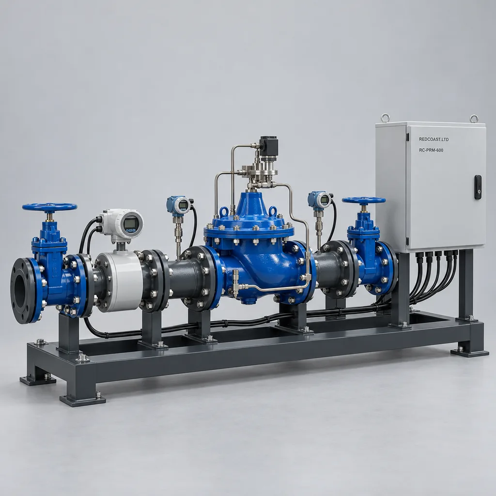
The RC-PRM-600 is a grid-powered smart water pressure management and district metered area (DMA) station for utilities, municipal estates, industrial parks, and large campuses. It combines a pilot-operated pressure reducing valve, inlet and outlet pressure measurement, bulk flow metering, an outdoor controller, a Web platform, and a mobile app in one configurable delivery. Operators can adjust distribution pressure to demand, investigate abnormal night flow, and document pressure changes without repeatedly entering a valve chamber. REDCOAST.LTD develops the station electronics and firmware, including project-specific PCBs, while selecting hydraulic valves and metrology components for the actual water duty.
Key Features
- Demand-based pressure settings: Select fixed pressure, time schedules, flow-based modulation, or bounded supervisory adjustment from a remote critical-point pressure sensor.
- Continuous hydraulic regulation: A motor-adjusted mechanical pilot regulates the main valve; electricity changes its setting rather than supplying the force that moves the main diaphragm.
- DMA measurement in one view: Correlate inlet pressure, outlet pressure, instantaneous flow, totalized volume, and operating mode on a common timeline.
- Local control during communication loss: Store schedules and limits at the station, reject stale remote commands, and record data for later upload.
- Purpose-built electronics: REDCOAST.LTD designs isolated pressure-input, actuator-interface, protected power-distribution, and edge-controller PCBs around project interfaces.
- Practical retrofit options: Retain a serviceable hydraulic valve or existing bulk meter after checking pilot compatibility, valve condition, signal format, and installation geometry.
- Controlled pressure changes: Apply configurable setpoint ramps, pressure limits, signal plausibility checks, and separate permissions for viewing and control.
- Serviceable outdoor construction: Separate mains terminals from low-voltage instrumentation, provide labeled test points, and keep the control cabinet accessible above the chamber.
- Auditable water management: Record configuration changes, operator actions, alarms, and maintenance notes for utility and contractor handover.
Technical Architecture
The hydraulic assembly contains isolation valves, an upstream strainer, a bulk electromagnetic meter, a diaphragm-operated pressure reducing valve, pressure tapping points, and a dismantling joint where required. Meter placement and straight lengths follow the selected meter's instructions; the meter must remain full of water. An electric pilot actuator changes spring loading or the equivalent mechanical pilot setting. The pilot and main valve then regulate downstream pressure hydraulically. Motor-adjusted pilots with analog commands and position feedback are an established industry approach, as illustrated by the Singer 420-DC/AC manufacturer specification.
The REDCOAST.LTD controller acquires isolated 4–20 mA pressure signals, meter data, actuator feedback, chamber-flood contacts, and door status. Its firmware checks signal validity before calculating a permitted pressure target from the selected operating mode. The electronic supervisory loop adjusts the pilot slowly enough to avoid fighting the faster hydraulic regulation, with commissioning-specific deadbands and ramp limits. A flow-based schedule uses a surveyed pressure-versus-demand table; it does not assume that valve position is a flow measurement. A remote critical-point signal can trim the local target only within approved limits and while its timestamp and quality remain valid.
The platform provides asset maps, trends, alarm acknowledgement, reports, and role-based access. The mobile app supports inspection records, commissioning readings, and authorized setpoint changes. If the network connection fails, the controller continues its approved local strategy; if a critical sensor fails, it suspends adaptive adjustment and applies the agreed fallback behavior. For the reference mechanical-pilot arrangement, loss of actuator power leaves hydraulic regulation at the retained mechanical setting, subject to the selected pilot's behavior and available upstream pressure. This principle is documented for comparable Cla-Val electronic pressure reducing valves; it must be demonstrated on the delivered valve assembly during acceptance.
Connectivity & Power
The reference station uses AC 100–240 V, 50/60 Hz from an existing utility or campus electrical service. An isolated 24 V DC supply powers the controller, instruments, and pilot actuator. Normal station demand is a design target of 20–35 W; actuator movement can raise input demand to 100 W, with a separately accounted 40 W cabinet heater bringing the reference maximum to 140 W. The main valve uses pipeline pressure as its operating energy. The electrical cabinet and image configurations therefore use mains wiring without photovoltaic equipment.
Ethernet is preferred where a managed utility network is available. A region-appropriate 4G LTE modem provides access at distributed sites, and Ethernet with cellular backup is an option for important stations. RS-485 Modbus RTU connects local instruments; MQTT over TLS and HTTPS carry platform traffic, while Modbus TCP is restricted to a protected operational network or VPN. The controller stores at least 365 days of one-minute trend records for 16 channels in the reference configuration; event logs and faster diagnostic captures have separate retention limits. Data uploads are configurable from 60 to 900 seconds, with immediate event transmission attempted when connectivity is available.
Protection & Reliability
The outdoor cabinet is specified to an assembled IP66 protection target, with sealed cable entries, a sunshield, protective earth bonding, and coordinated surge protection. Its standard steel construction uses hot-dip galvanizing beneath a smooth matte powder-coated topcoat, normally light grey RAL 7035 to reduce solar heat absorption. A coated stainless-steel enclosure and corrosion-resistant fittings can be selected for coastal installations. Corrosion exposure, coating preparation, drainage, and local anchorage loads are reviewed together; an ingress rating alone does not establish salt-spray resistance or wind performance.
The electronics operating envelope is a design target of -20 to +55 °C ambient with the selected thermal package and sunshield. The hydraulic package has a separate +2 to +50 °C water envelope: a warm cabinet does not prevent exposed valves, sensing lines, or stagnant pipework from freezing. Floodable chamber instruments require their own documented immersion depth and duration, while the main cabinet remains above the project flood level. Maintenance planning covers pilot strainers, diaphragms, pressure calibration, meter diagnostics, cable seals, and actuator travel. Service life and warranty terms are confirmed against the chosen bill of materials, water chemistry, environment, and maintenance plan.
Application Scenarios
Urban district metered areas. Install the station at a pressure-zone inlet where electrical service already exists. Operators can compare night flow with legitimate consumption and adjust pressure schedules while checking the minimum pressure at the network's critical point.
Industrial park water distribution. Place a station between a higher-pressure supply main and a shared tenant network. Pressure and volume records help distinguish demand changes from supply problems and give maintenance teams a common operating history.
Campus and institutional estates. Use local pressure control on an estate branch serving teaching buildings, accommodation, or public facilities. Scheduled operation can accommodate changing occupancy, subject to the hydraulic requirements of the highest or most distant outlets.
Reclaimed-water irrigation distribution. Install the package on a filtered reclaimed-water trunk feeding several landscape irrigation controllers. It stabilizes the distribution supply as irrigation blocks start and stop, while the existing irrigation controllers continue to manage watering schedules and individual zones.
Existing valve-chamber modernization. Add a compatible actuator, instruments, and an above-ground control cabinet to a suitable mechanical PRV installation. This reduces routine chamber entry for adjustment and gives operators evidence of pressure behavior between maintenance visits.
Case-style Examples
These examples illustrate engineering configurations and intended acceptance outcomes; they are not claims of completed customer projects or measured savings.
Neighborhood pressure-zone retrofit. A distribution branch has approximately 6 bar inlet pressure and a surveyed demand range of 10–65 m³/h. A DN100 reference station uses a bulk meter, two pressure transmitters, Ethernet with cellular backup, and proposed outlet targets of 3.8 bar during higher demand and 2.8 bar overnight. Before enabling the lower setting, commissioning verifies at least 1.8 bar at the identified critical point under the agreed demand conditions. Acceptance compares pressure stability and normalized night-flow records; any leakage improvement is measured after deployment.
Shared landscape-water header. A campus operates several irrigation controllers from an 8 bar reclaimed-water main, with combined demand of approximately 20–120 m³/h. A DN150 station targets 4.5 bar downstream and exchanges status with the existing irrigation platform; filtered-water compatibility, elastomers, and pilot-strainer servicing are specified in the package. The intended result is a documented supply-pressure envelope as irrigation blocks change, with alarms for supply loss or unexpected flow. It does not replace filtration, water treatment, or irrigation scheduling.
Customization & Selection Guide
Start with minimum, normal, and maximum flow; inlet-pressure variation; required outlet pressure; elevation differences; water quality; and the existing pipeline drawing. Select the valve using its flow coefficient, minimum stable flow, available differential pressure, and cavitation chart. A nominal pressure class is not permission to operate every inlet/outlet combination: high pressure drops may require anti-cavitation trim or two-stage reduction, and very low night demand may require a smaller parallel regulating branch. The reference family covers DN50–DN300, with a pipe-sizing guide of 0.3–3.0 m/s; actual valve duty is checked separately.
Choose a basic package with two local pressure sensors and fixed or timed control when budgets are limited. Add a calibrated flow meter for demand modulation and DMA reporting, then add remote critical-point feedback only where its communication reliability and hydraulic value justify the additional equipment. Commercial pressure controllers already use time and flow modulation, supporting these as practical selection categories rather than speculative features. See the HWM Pegasus 2 product description.
The reference electromagnetic meter procurement target is ±(0.5% of reading plus the flow equivalent of 1 mm/s), under its specified reference conditions. This reflects a published industrial specification, not a guaranteed station-wide accuracy or a promise of the same percentage error at near-zero flow. Meter conductivity limits, grounding, straight lengths, full-pipe conditions, and calibration remain binding; see the Endress+Hauser Promag W 400 specification. Billing applications require a separately selected, approved metering configuration. Pressure-sensor selection also distinguishes non-linearity from total reference-condition error: the WIKA A-10 datasheet dated February 2026 shows why a non-linearity figure should not be presented as installed-system accuracy.
Deployment & After-sales
Delivery can include a prefabricated hydraulic assembly with a separate cabinet, or a surveyed retrofit kit with installation drawings. Site work includes isolation planning, foundation and pipe supports, flushing, electrical protection, earthing, meter grounding, sensor calibration, and confirmation of the allowed pressure envelope. Commissioning begins at an approved fixed setting, then tests scheduled changes, loss of communications, sensor faults, power interruption, and restoration before adaptive operation is enabled. Fire-water branches and other critical consumers require their own hydraulic review and locally available override strategy; the controller is not presented as a certified fire-protection control system.
For procurement planning, allow approximately 8–12 weeks after design freeze for a configured package using available components; a new PCB variant, unusual valve trim, or additional qualification can extend that estimate. The quotation confirms the actual schedule and warranty. Handover includes wiring and hydraulic diagrams, I/O maps, firmware and configuration versions, calibration records, operating instructions, and an agreed spare-parts list. Remote diagnostics, operator training, replacement electronics, and support for the customer's SCADA integration can be included in the service scope.
Standards & Compliance
The figures in this page define a proposed, made-to-order reference configuration. They are not substitute test reports: the contracted assembly, performance limits, and applicable approvals are confirmed during engineering and acceptance.
Hydraulic control-valve requirements are assessed against EN 1074-5, control valves for water supply, with the selected pressure class, materials, and operating conditions documented. Metering requirements may reference ISO 4064-1:2024; legal-for-trade use depends on the meter's approval and the rules at the installation location. Potable-water builds require documented approvals for the actual wetted components. Lead-content assessment and extraction testing are distinct requirements, as explained by NSF's December 2025 guidance on NSF/ANSI/CAN 372 and 61.
Enclosure ingress tests are specified under IEC 60529. Where no more specific product standard applies, an industrial EMC plan can use IEC 61000-6-2 immunity and IEC 61000-6-4 emissions; installations near residential users require the appropriate environment-specific assessment. Electrical safety, radio approvals, material restrictions, and any required conformity marking are scoped for the destination and final configuration. Component certificates do not automatically certify the complete station.
Why REDCOAST.LTD
REDCOAST.LTD delivers the hydraulic control package, outdoor electronics, firmware, Web platform, mobile app, and integration engineering as one coordinated solution. In-house PCB and board-level design makes it possible to change sensor interfaces, isolation arrangements, actuator feedback, I/O counts, cabinet layout, and communications to fit an existing utility environment. That capability is especially useful when a standard telemetry box cannot accommodate an established valve or operating workflow. The project remains tied to a documented hydraulic duty, a traceable hardware configuration, and practical acceptance tests.
Send REDCOAST.LTD your pipeline size, flow profile, inlet and target pressures, water type, site drawing, and integration requirements to request a tailored RC-PRM-600 configuration and quotation.
Specifications
Hydraulic Duty — Reference Configuration
- Nominal Pipe Sizes
- DN50, DN80, DN100, DN150, DN200, DN250, DN300 mm
- Assembly Pressure Class
- PN16 at 20 °C; total pressure including surge must remain within the selected assembly rating
- Design Inlet Pressure
- 3–12, gauge; each inlet/outlet duty requires cavitation and valve-sizing review bar
- Downstream Setpoint Range
- 1.5–8, gauge; requires adequate inlet pressure and a compatible pilot spring range bar
- Reference Minimum Operating Differential
- 1.0; selected valve and flow duty may require more bar
- Water Temperature
- +2 to +50; all wetted sections protected against freezing °C
- Pilot Arrangement
- 1 motor-adjusted mechanical pressure-reducing pilot, 24 V DC actuator, hydraulic main-valve operation
- Reference Wetted Materials
- Epoxy-lined ductile iron body; stainless-steel trim; EPDM diaphragm and seals
Pressure & Flow Measurement
- Pressure Measurement Points
- 2 local: inlet and outlet; 1 optional remote critical point points
- Pressure Transmitter Ranges
- 0–10 or 0–16, gauge, with 4–20 mA output bar
- Pressure Transmitter Procurement Accuracy
- Maximum error ±0.5% of span at reference temperature; temperature drift assessed separately
- Reference Flowmeter
- Full-bore electromagnetic, DN50–DN300, bidirectional flow and totalization
- Flowmeter Procurement Accuracy
- ±(0.5% of reading + flow equivalent of 1 mm/s), under meter reference conditions
- Pipe-Sizing Velocity Guide
- 0.3–3.0; not a guaranteed valve operating range m/s
- Minimum Water Conductivity
- 5 for the reference electromagnetic-meter selection; selected meter specification governs µS/cm
Local Control & Field I/O
- Control Modes
- 4: fixed pressure, timed schedule, flow modulation, bounded critical-point supervision
- Analog Inputs
- 6 isolated channels, 4–20 mA
- Analog Outputs
- 2 isolated channels, 4–20 mA for compatible pilot interfaces
- Digital Inputs
- 8 dry-contact inputs for status, flood, tamper, and interlocks
- Relay Outputs
- 4 dry contacts, rated 1 A at 24 V DC resistive; signal duty
- Pressure Setpoint Ramp
- 0.02–0.20; commissioning selects the permitted rate bar/min
- Local Pressure Acquisition
- 10 samples per second; supervisory adjustment every 1–60 seconds, default 10 seconds
- Remote Feedback Stale Timeout
- 30–300, followed by the approved local fallback strategy s
Mains Power — Reference Load Budget
- Input Voltage
- AC 100–240, single phase V
- Input Frequency
- 50/60 Hz
- Internal DC Supply
- 24 V DC, 150 W nominal; thermal derating checked against the selected cabinet conditions
- Normal Power Consumption Target
- 20–35, including controller, HMI, modem, two pressure sensors, and reference meter W
- Actuator-Movement Input Target
- Up to 100 for the reference package, excluding cabinet heater W
- Heater & Maximum Input Target
- 40 W thermostatic cabinet heater; up to 140 W total with actuator moving W
Communications & Data
- Ethernet
- 1 × 10/100BASE-T
- Cellular Option
- 4G LTE Cat 1 or Cat 4; modem bands and approvals selected for deployment
- Instrument Serial Ports
- 2 isolated RS-485 ports, Modbus RTU, 9.6–115.2 kbit/s
- Platform Protocols
- MQTT over TLS 1.2 or later; HTTPS API; Modbus TCP on protected LAN/VPN
- Local Storage Target
- 8 GB industrial flash; at least 365 days of 1-minute trends for 16 channels
- Upload Interval
- 60–900; event upload attempted immediately when connected s
Enclosure & Environmental Design Targets
- Cabinet Ingress Protection
- IP66 target for the assembled cabinet with specified glands and closed door
- Electronics Ambient Range
- -20 to +55 with selected thermal package and sunshield; water temperature limits remain separate °C
- Relative Humidity
- 5–95, non-condensing inside the electronics compartment %
- Reference Cabinet Dimensions
- 600 × 500 × 250, height × width × depth, excluding plinth and sunshield mm
- Steel Cabinet Finish
- Hot-dip galvanized substrate with smooth matte powder-coated RAL 7035 topcoat
- Reference Mechanical Layout
- 1 lockable cabinet; segregated mains and low-voltage terminals; bottom cable entry
Platform & Operational Tools
- Operator Interfaces
- Web dashboard; Android/iOS app; local 7-inch HMI inside the cabinet
- Access Roles
- 3 standard roles: viewer, operator, administrator
- Alarm Categories
- High/low pressure, abnormal flow, sensor fault, stale data, cabinet intrusion, chamber flooding
- Audit Log Capacity Target
- At least 100,000 local entries for commands, settings, acknowledgements, and service actions entries
- Data Export
- CSV trend export; HTTPS API; timestamp, engineering unit, and quality flag per measurement
- Firmware Maintenance
- Signed update packages, version history, and controlled rollback to the prior approved image
Capabilities — configurable per project
Specifications are tailored to each project — the options below show what we can support.
Hydraulic Arrangement
- Single regulating valve
- Parallel low-flow regulating branch
- Two-stage pressure reduction
Metering Package
- Operational electromagnetic bulk meter
- Approved billing meter with required local verification
- Existing pulse or Modbus meter integration
Network Connection
- Managed Ethernet
- 4G LTE cellular
- Ethernet with cellular backup
Enclosure Package
- Duplex-coated steel outdoor cabinet
- Smooth-painted 316L stainless-steel coastal cabinet
- Indoor wall-mounted control panel
Software Deployment
- Managed private cloud
- Customer-hosted platform
- Existing SCADA integration with local control
Related solution guidance

Environmental Monitoring
Deploy environmental monitoring stations with sensors, solar power, gateways, dashboards, alarms and data integration for city and industrial sites.

Street Lighting Guide
A practical guide to choosing smart street lighting controllers, connectivity, platform features, dimming logic and acceptance tests.
Solar IoT Guide
A design guide for solar-powered outdoor IoT: load calculation, battery autonomy, low-power firmware, telemetry and maintenance planning.
Frequently Asked Questions
What does a smart water pressure management station do?
It measures supply pressure, downstream pressure, and water flow, then adjusts a pressure reducing valve to an approved operating target. The RC-PRM-600 combines this control with local records, remote alarms, a Web platform, and a mobile app. It can support pressure and leakage management, but actual savings depend on the network and must be measured.
Can the RC-PRM-600 retrofit an existing pressure reducing valve?
Yes, when the valve body, diaphragm, pilot arrangement, and minimum-flow behavior are suitable for the intended duty. REDCOAST.LTD checks the exact valve model, pressure envelope, actuator interface, and available chamber space before defining the retrofit. An unsuitable or heavily worn valve may require replacement even if remote telemetry can be added.
What happens if mains power or the internet connection fails?
With mains available but no internet connection, the controller continues the approved local schedule and buffers records. In the reference motor-adjusted mechanical-pilot configuration, loss of electrical power leaves hydraulic regulation at the retained pilot setting, provided upstream pressure remains adequate. Telemetry and electric setpoint changes stop until power returns, and the exact hydraulic response is verified during acceptance.
Can one station cover both very low night flow and peak demand?
Only if the selected valve and meter cover the required operating envelope. A valve sized for peak demand may be unstable at very low flow, so a smaller parallel regulating branch or suitable low-flow trim may be needed. Pipe diameter alone does not establish control range or measurement accuracy.
Does DMA metering mean the station can bill customers?
The standard operational-metering package provides flow trends and volume records for network management. Revenue billing requires a meter and installation with the applicable metrological approval and local verification. Exporting data to billing software does not itself make the measurement legally approved.
Can the station serve potable water and reclaimed irrigation water?
Separate configurations can be engineered for either duty, with wetted materials, seals, filtration, and maintenance selected accordingly. Potable-water projects require documented approvals for the actual components in contact with water. Reclaimed-water installations remain hydraulically separated from drinking-water systems and may need additional protection against pilot fouling.
What should a buyer provide for an accurate quotation?
Provide minimum and peak flow, inlet-pressure variation, required downstream pressure, water temperature and quality, pipe size, flange details, and a site drawing. Include critical-point elevations, available mains power, communications, and any existing PRV or meter model. REDCOAST.LTD uses these inputs to define the hydraulic package, custom electronics, integration scope, and acceptance tests.