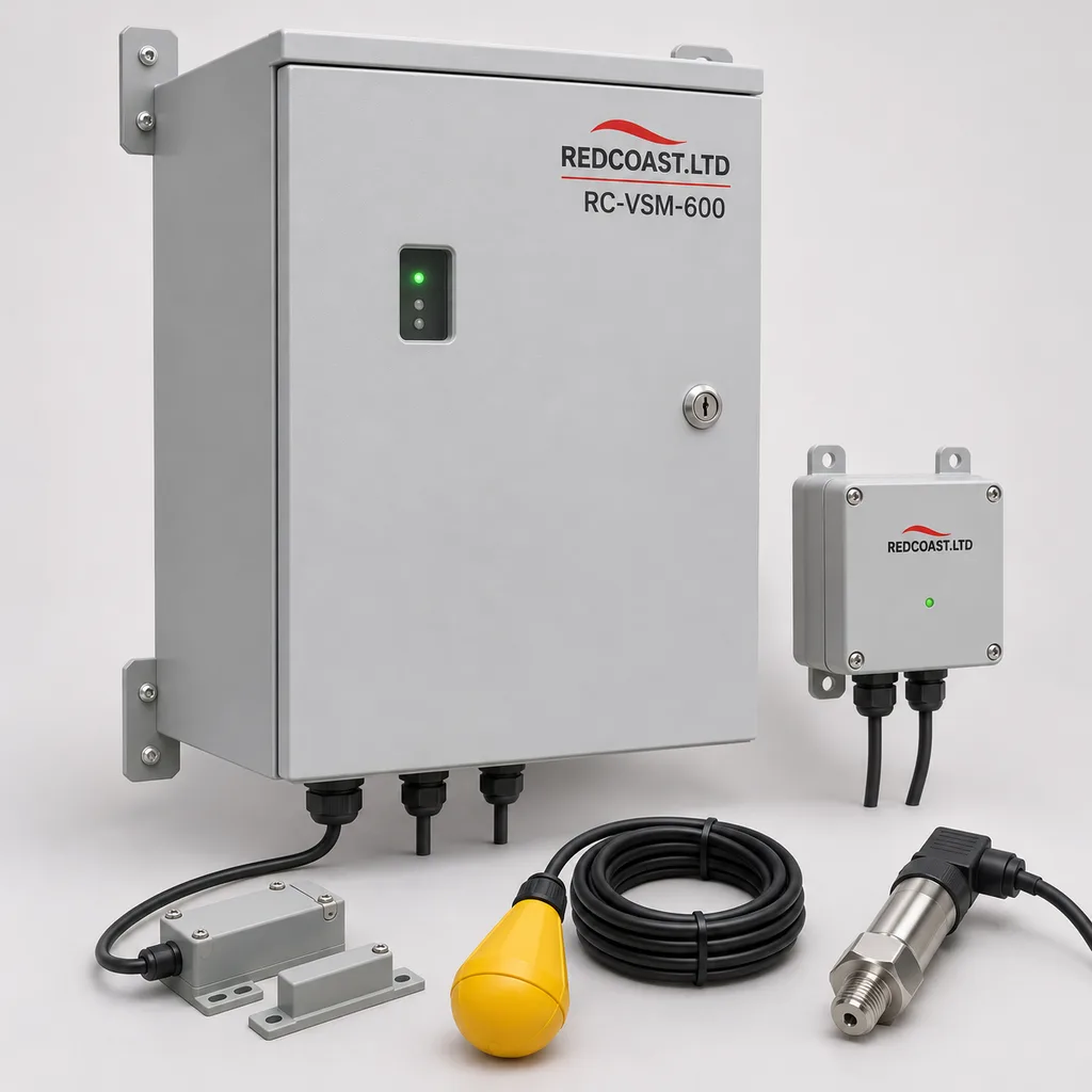
Overview
The RC-VSM-600 is a mains-powered vacuum sewer valve monitoring system from REDCOAST.LTD, combining field instrumentation, an edge gateway, Web management and a mobile maintenance app. It helps municipal wastewater utilities, estate operators and infrastructure integrators identify which collection pit needs attention when a valve remains open, a sump reaches its high-level switch or a branch loses vacuum. Designed for new developments and existing networks with usable cable routes, it connects up to 64 monitoring nodes to one gateway and leaves the original pneumatic valve operation under its existing controller. The specifications below define a configurable engineering design basis for project quotation; final performance, environmental ratings and compliance are established for the supplied configuration during qualification and acceptance.
Key Features
- Individual valve event records: Capture opening and closing transitions, cycle counts and open duration with a 100 ms timestamp resolution, allowing technicians to compare current behavior with an established baseline.
- Separate high-level warnings: Connect an independent sump high-level switch so an abnormal liquid level remains visible even when the valve-position signal appears normal.
- Branch vacuum visibility: Add 4–20 mA transmitters with a −100 to 0 kPa gauge-pressure range at selected branch ends or intermediate points.
- Local fault processing: Apply configurable persistence, debounce and maintenance suppression rules at the gateway, preserving local detection during an internet outage.
- Four protected field segments: Divide up to 64 nodes across four isolated RS-485 channels, with separately protected 24 V supplies and segment health reporting.
- Mapped maintenance workflow: Associate each node with a surveyed pit location, access notes, alarm history and an app-based maintenance record.
- Open integration: Export operating data through Modbus TCP, MQTT over TLS and an HTTPS API for utility SCADA, asset management and reporting.
- Project-specific electronics: REDCOAST.LTD develops the monitoring node PCB, isolated acquisition interfaces, gateway carrier and power-distribution circuitry around the required sensors, installation geometry and service procedures.
Technical Architecture
A complete installation includes the RC-VSM-600 gateway cabinet, RC-VSM-N1 field nodes, valve-position sensors, sump high-level switches and selected vacuum-pressure transmitters. Each node provides four supervised contact inputs and one 4–20 mA input. Typical contact assignments are valve position, sump high level, access-cover status and a spare service input. Position is obtained from an existing approved monitoring contact or a mechanically qualified external sensor bracket; it is not inferred solely from pump runtime. The base node belongs in an accessible, non-hazardous surface enclosure. Sensors entering a classified chamber require an appropriately assessed interface arrangement.
The node timestamps transitions locally and maintains a persistent event queue. The gateway polls the four field segments, checks missing-device and circuit-fault conditions, then calculates open duration, hourly cycles and pressure recovery trends. A held-open warning requires the configured open-duration threshold to be exceeded; high sump level with little valve activity produces a different diagnostic indication. Thresholds are commissioned against the installed valve type, loading pattern and hydraulic design. These measurement categories are established industry practice, illustrated by vacuum sewer monitoring documentation. RC-VSM-600 applies them through its own specified hardware and software configuration.
The gateway retains operating history locally and forwards timestamped records to the Web platform. The mobile app presents the affected pit, supporting evidence and an acknowledgement workflow, while SCADA receives quality flags as well as values. Rainfall-correlated cycle increases can prioritize infiltration investigations, but cycle count alone is not a calibrated wastewater volume measurement. Pressure changes can narrow an investigation to an instrumented branch; they do not identify an exact underground leak coordinate. Automatic vacuum-valve actuation and pump-speed control are outside the base monitoring package.
Connectivity & Power
The standard cabinet accepts AC 100–240 V at 50/60 Hz and distributes nominal 24 V DC to the field nodes. A 150 W DC supply provides capacity for the gateway, up to 64 nodes and the specified optional 40 W condensation heater, subject to the final load and cable-loss schedule. The cabinet requires a continuously energized utility feeder. Pump motors use their existing electrical supply and are outside the monitoring power budget.
The reference field layout uses four daisy-chain RS-485 segments, each with up to 16 nodes. A preliminary segment allowance is 250 m using a shielded data pair and separate 2.5 mm² copper power conductors, with no more than 16 W of connected node load. This is a design starting point: conductor temperature, joints, surge protection and the actual load distribution must leave at least 18 V at every node. Longer routes require recalculated cabling or additional locally powered gateways. Termination, reference conductors and shield bonding follow the installation design.
Ethernet serves sites with an operations network; an optional 4G LTE modem provides backhaul where a wired uplink is unavailable or requires redundancy. Cellular frequency bands and carrier acceptance are selected for the installation country. Modbus remains on a segregated utility network, while remote services use authenticated encrypted connections. Internet loss leaves local acquisition operating while power remains available; loss of site power interrupts monitoring and is shown as stale data after the supervisory heartbeat expires. The original pneumatic system retains its existing operating behavior.
Protection & Reliability
The cabinet design targets IP66, with bottom cable entries, replaceable seals, a lockable door and an internal mains segregation barrier. Its fabricated steel shell receives hot-dip galvanizing followed by a smooth matte powder-coated finish; RAL 7035 light grey and RAL 7016 anthracite are standard appearance options. Field-node housings use UV-stabilized polycarbonate. Selected immersed sensor assemblies target IP68 under a defined 2 m, 72-hour freshwater qualification condition; this does not make the surface cabinet submersible or establish chemical compatibility.
The reference ambient envelope is −20 to +55 °C for a shaded, ventilated installation location, with a sealed cabinet and no dependence on outdoor air passing through the electronics compartment. Direct sun, salt exposure, flood elevation and local wind loading are reviewed through enclosure, coating and mounting selection. Conformal coating, protected field ports, a hardware watchdog and replaceable terminal modules support serviceability, but do not establish a fixed service life. Inspection intervals, spare-part availability and warranty coverage are specified in the project maintenance agreement.
Application Scenarios
New residential wastewater networks
Install monitoring conduits alongside new vacuum sewer mains and allocate a node to each collection pit. Operators receive pit-specific valve and high-level information from the start of service, making commissioning records useful for later fault investigation.
Business parks and institutional campuses
Use existing service corridors and local mains distribution to monitor vacuum sewer branches serving offices, accommodation and shared facilities. Facilities staff can distinguish a local pit alarm from a wider branch vacuum problem before dispatching a maintenance team.
Waterfront developments with vacuum collection
Place gateway cabinets above the design flood elevation and monitor collection pits along a developed waterfront. Selected pressure points and independent high-level switches help operators prioritize inspections after heavy rainfall or unusual system loading.
Holiday estates and seasonal visitor facilities
Track valve activity across accommodation clusters whose wastewater loads change substantially between occupied and quiet periods. Separate operating baselines and maintenance modes help avoid treating normal seasonal variation as a confirmed defect.
Existing systems with reusable monitoring ducts
Replace obsolete telemetry using surveyed cable routes and compatible sensor interfaces. A staged rollout allows operators to compare the new event records with existing station information before extending coverage.
Case-style Examples
The following are illustrative configurations and intended operational outcomes, not claims of completed REDCOAST.LTD installations.
A 48-pit estate commissioning package
A newly built estate needs pit-level records before occupancy increases, and monitoring ducts are included in the civil works. One gateway serves four 12-node segments, with a valve contact and high-level switch at every pit and a vacuum transmitter at each branch end. Acceptance demonstrates that a simulated held-open contact is assigned to the correct pit and appears in the local interface and connected SCADA, giving the operator a documented dispatch workflow.
A 96-pit legacy telemetry renewal
An operator has usable cable ducts but receives only a general low-vacuum alarm from the existing station. Two gateways divide the estate into eight 12-node segments, and existing contacts are retained only after mechanical and electrical compatibility checks. The intended result is an event timeline that separates a persistent valve-open indication from loss of communications or a high-level condition; no fixed reduction in maintenance cost is assumed.
Customization & Selection Guide
Start with a pit schedule, valve makes and models, route lengths, existing cable details, station interface information and hazardous-area drawings. Fit valve-position and high-level sensing to every monitored pit, then place pressure transmitters where the hydraulic layout makes them diagnostically useful. A basic installation can omit most analog sensors while retaining individual valve records and level alarms.
This wired configuration is most practical when conduits already exist or trenches are open during construction. Established suppliers describe both the use of wired monitoring and the difficulty of adding new buried cables to some older estates in their installation guidance. If suitable routes are absent, include civil-work cost in the comparison before selecting this model. Different sensor brackets, contact polarities and pressure connections require a compatibility review; support for one valve family does not establish compatibility with every manufacturer's valve.
For software, choose customer-hosted deployment or managed hosting, then define operator roles, retention, alarm recipients and API permissions. Scale larger networks using additional gateways close to the relevant cable clusters, rather than extending a single power circuit without checking voltage drop.
Deployment & After-sales
Delivery begins with the signal schedule, site layout, electrical load calculation and agreed alarm matrix. REDCOAST.LTD then develops or adapts the board-level interfaces, enclosure assembly, firmware and platform configuration. A representative pilot is used before fleet production when the valve interface, hazardous-area arrangement or communications path is new.
Factory acceptance covers contact transitions, analog calibration, alarm persistence, cable faults, restart behavior and data export. Site acceptance verifies every pit identity, high-level input, far-end voltage and station data mapping under the agreed test conditions. Sensors are installed through approved access procedures and do not replace confined-space precautions.
The quotation separates engineering, prototype qualification, production and site commissioning milestones; lead time is confirmed after design freeze and component review. Handover includes wiring drawings, a register map, calibration records, configuration backups and service instructions. Remote diagnostics, firmware maintenance, replacement nodes and installer training can be included in the support agreement.
Standards & Compliance
The sewer-system design and acceptance reference is EN 16932-3:2018, covering vacuum drainage and sewer pumping systems outside buildings. Adding telemetry does not establish compliance of the complete sewer installation.
Enclosure qualification is specified against IEC 60529. The electrical safety assessment uses IEC 61010-1 where applicable, and the EMC plan uses IEC 61326-1:2020 for measurement and control equipment. The test plan defines configuration, cable ports, operating modes and pass criteria before testing.
The base equipment is for non-hazardous locations. Where sensors or circuits enter explosive atmospheres, the project requires appropriately certified apparatus, barriers and a documented installation assessment; IEC 60079-11 addresses equipment protection by intrinsic safety. An IP rating does not provide explosion protection. Destination-specific conformity documentation, including applicable CE, RoHS and radio requirements, is scoped to the final supplied assembly; no certification is asserted by this concept specification.
Why REDCOAST.LTD
REDCOAST.LTD delivers the field hardware, gateway firmware, Web platform and mobile app as one project. Its ability to design new PCBs and board-level hardware makes it possible to adapt sensor excitation, isolation, connectors, protected power outputs and enclosure geometry to the actual installation. This is useful when a utility needs a maintainable replacement for obsolete telemetry or a consistent interface across several qualified valve types. Project-specific engineering is backed by documented acceptance criteria, so customization remains tied to measurable operating requirements.
Contact REDCOAST.LTD with your pit count, valve details, cable-route plan and SCADA requirements to request a tailored RC-VSM-600 configuration and quotation.
Specifications
System Configuration
- Field-node capacity per gateway
- 16 / 32 / 64 nodes
- Isolated field segments
- 4
- Maximum nodes per segment
- 16 nodes
- Supervised contact inputs per node
- 4 channels
- Analog input per node
- 1 x 4–20 mA
- Local transition timestamp resolution
- 100 ms
- Persistent event queue per node
- 4,096 events
Measurement & Alarm Settings
- Optional vacuum transmitter range
- −100 to 0, gauge pressure kPa
- Pressure measurement accuracy target
- ±1.0% of 100 kPa span at 23 ±5 °C, after loop calibration
- Pressure acquisition interval
- 1 s
- Held-open alarm threshold
- 5–300, commissioned for the installed valve s
- High-level alarm persistence
- 1–60 s
- Contact debounce adjustment
- 20–500 ms
- Healthy-bus event delivery target
- ≤5 to the local gateway, excluding alarm persistence and WAN transit s
Mains Power & Distribution
- AC input voltage
- 100–240 V AC
- Input frequency
- 50/60 Hz
- DC power supply rating
- 24 V DC / 150 W
- Gateway assembly consumption
- 15 typical / 25 maximum, excluding field loads and heater W
- Field-node consumption
- 0.25 typical with contact sensing; 1.0 maximum including one specified pressure transmitter W
- Field-node input range
- 18–30 V DC
- Maximum configured system input
- 180, including 64 nodes, cable losses and optional 40 W heater W
- Field output protection
- 4 separately protected branches; 1.0 A electronic current limit per branch
Communication & Cabling
- Field protocol
- Modbus RTU over isolated RS-485
- Serial data-rate options
- 9,600 / 19,200; 19,200 reference configuration bit/s
- Reference segment length
- 250 with ≤16 W node load; far-end supply ≥18 V m
- Reference cable construction
- Shielded 120-ohm data pair, reference conductor and 2 x 2.5 mm² copper power conductors
- Ethernet interface
- 1 x 10/100BASE-T
- Optional cellular uplink
- 4G LTE Cat 1; destination-specific bands and carrier profile
- SCADA and platform interfaces
- Modbus TCP / MQTT over TLS 1.2 or later / HTTPS API
Enclosure & Environment
- Cabinet ingress-protection target
- IP66, closed and correctly gland-sealed
- Surface-node housing target
- IP66; UV-stabilized polycarbonate; non-hazardous location
- Selected immersed sensor sealing target
- IP68; 2 m freshwater immersion for 72 h with specified cable assembly
- Reference ambient range
- −20 to +55; shaded cabinet location °C
- Gateway cabinet dimensions
- 600 x 450 x 250, height x width x depth, excluding mounting hardware mm
- Steel cabinet finish
- Hot-dip galvanized base with smooth matte powder coat; RAL 7035 or RAL 7016
- Optional condensation heater
- 40, thermostat controlled W
- Surface-node dimensions
- 180 x 120 x 80, excluding glands; external barriers may require a larger enclosure mm
Data, Software & Maintenance
- Gateway local storage
- 8 GB
- Local history retention target
- ≥30 at 64 nodes, one-minute summaries and 100,000 additional event records days
- Routine upload interval
- 1–60; alarms forwarded on detection while connected min
- Clock synchronization
- NTP from a configured utility or network time source
- Primary operator roles
- Viewer / Operator / Maintainer / Administrator
- Data export formats
- CSV / JSON
- Maintenance interface
- Local browser interface plus Web platform and mobile app
Capabilities — configurable per project
Specifications are tailored to each project — the options below show what we can support.
Coverage package
- 16-pit starter package
- 32-pit district package
- 64-pit gateway package
Instrumentation
- Valve-position contacts and high-level switches
- Add branch-end vacuum transmitters
- Add access-cover contacts and station telemetry mapping
Backhaul
- Ethernet
- Ethernet with 4G LTE fallback
- Fiber uplink through an industrial media converter
Installation format
- Wall-mounted RAL 7035 cabinet
- Pedestal-mounted RAL 7016 cabinet
- Sheltered installation with a 40 W condensation heater
Software deployment
- Customer-hosted Web platform
- Managed hosting with mobile maintenance app
- Existing SCADA integration with API data export
Related solution guidance
Environmental Monitoring
Deploy environmental monitoring stations with sensors, solar power, gateways, dashboards, alarms and data integration for city and industrial sites.
Power and Connectivity
How to choose power, battery, solar, NB-IoT, LTE, LoRaWAN, gateways and monitoring strategy for outdoor IoT infrastructure.
Campuses
Campus IoT for lighting, parking, safety, smart poles, environmental data and facility maintenance workflows.
Frequently Asked Questions
What does a vacuum sewer valve monitoring system detect?
RC-VSM-600 records valve openings, closings and open duration, and monitors independent high-level switches in collection pits. Optional pressure transmitters show vacuum conditions at selected network points. Combined alarms help identify the affected pit or branch for inspection; they do not automatically prove the underlying mechanical defect.
How is this different from a smart manhole level sensor?
A general manhole sensor primarily reports chamber conditions such as liquid level or cover movement. RC-VSM-600 adds valve-cycle timing and branch vacuum trends specifically for pneumatic vacuum sewer networks. It can distinguish a persistent valve-open indication, a high-level condition and missing telemetry as separate events.
Does every collection pit need a mains connection?
The gateway cabinet needs a continuous AC 100–240 V supply, while its field nodes receive nominal 24 V DC over designed power cables. The reference layout allows up to 16 nodes per 250 m segment with specified cable construction and a verified far-end voltage of at least 18 V. Larger or more dispersed networks use additional powered gateways; the existing pneumatic valve does not receive its operating energy from this monitoring supply.
Can it monitor valves from different manufacturers?
A retrofit is possible when the installed valve offers a suitable monitoring contact or accepts a qualified external position sensor. REDCOAST.LTD can design mounting brackets, input circuitry and connector arrangements around an approved interface. Compatibility is confirmed for each valve model and revision, including mechanical clearance and any hazardous-area requirements.
Can valve cycle counts measure wastewater flow or prove infiltration?
Cycle count and duration are diagnostic indicators, not inherently accurate volumetric measurements. Wastewater volume per cycle can change with operating conditions, and excess activity can have several causes. Rainfall correlation can identify locations worth investigating, while quantified flow or confirmed infiltration requires additional measurements and field checks.
What happens if the internet connection or site power fails?
With mains power available, the gateway continues acquiring data and evaluating local alarms during an internet outage, then uploads stored records when connectivity returns. A site power failure stops monitoring unless the facility already supplies the cabinet from a backed-up feeder. Supervisory software marks missing updates as stale, and the sewer valves retain their existing pneumatic control behavior.
Is IP66 or IP68 equipment automatically suitable for explosive sewer atmospheres?
No; ingress protection and explosion protection address different hazards. The base gateway and field nodes are specified for non-hazardous locations. Circuits entering classified chambers require appropriately certified sensors or assessed simple apparatus, suitable barriers and a documented system assessment before installation.
What information is needed for an accurate quotation?
Provide the number of pits, valve makes and models, route drawings, cable sizes and lengths, available power and required SCADA protocols. Include the hazardous-area assessment, expected flood level, climate conditions and desired hosting arrangement. These details determine node interfaces, pressure-sensor locations, gateway distribution, qualification work and delivery milestones.