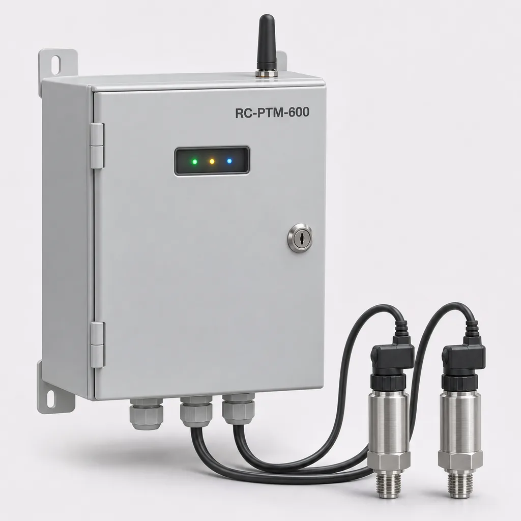
Overview
The RC-PTM-600 is a mains-powered water hammer and pressure transient monitoring station for irrigation operators, water utilities, industrial estates and infrastructure integrators. It records rapid pressure changes around pump starts, pump stops, check-valve closure and irrigation-zone switching, helping maintenance teams investigate problems that slow trend logs can miss. REDCOAST.LTD supplies the measurement hardware, outdoor cabinet, Web management platform and mobile App as one configurable solution. The station combines continuous local acquisition with event waveform capture and operational context, so engineers can compare pressure excursions with actual equipment activity. Specifications below describe the proposed project configuration and acceptance targets; final performance is confirmed for the ordered assembly during engineering and testing.
Key Features
- Simultaneous pressure capture: Two pressure channels as standard, expandable to four, with selectable acquisition at 100, 250 or 1,000 samples per second per channel.
- Event history with context: A circular buffer retains pressure data before a trigger, followed by an adjustable recording period that shows the immediate excursion and subsequent recovery.
- Positive and negative pressure investigation: Gauge and compound-range transmitters capture overpressure and sub-atmospheric excursions within their selected measurement spans.
- Equipment-state correlation: Four digital inputs associate pressure traces with pump-run contacts, drive faults or valve limit switches; two inputs can alternatively count flow-meter pulses.
- Local operation through network outages: Acquisition, triggering and storage run in the cabinet while the Web platform receives queued records after connectivity returns.
- Useful engineering outputs: Waveform overlays, pressure extrema, event counts, rate-of-change trends and CSV exports support investigation and comparison after maintenance.
- Custom board-level hardware: REDCOAST.LTD develops the analog acquisition, isolated field-interface and power-supervision PCBs to suit the project's sensors, enclosure and integration requirements.
- Practical installed package: Mains power, Ethernet, optional LTE telemetry and a coated outdoor cabinet suit permanently instrumented pump houses and accessible pipeline sites.
Technical Architecture
The field assembly comprises pressure transmitters, short process connections, shielded sensor cables and a cabinet containing the acquisition board, edge processor, industrial storage and protected AC/DC supply. The standard analog interface accepts matched 4–20 mA transmitters. Each pressure channel has input protection, current-to-voltage conversion and filtering ahead of simultaneous conversion; the field acquisition section is isolated from the communications domain. Sensor speed is specified separately from converter speed: the 1,000-sample/s configuration requires a transmitter with a specified settling time of 1 ms or less and a suitably direct hydraulic connection. Industrial transmitters with fast-response options are commercially established, as illustrated by WIKA's S-20 technical documentation. A faster converter cannot recover detail already removed by a damped transmitter or a restrictive pressure tapping.
The edge processor continuously evaluates high pressure, low pressure, pressure rate of change and selected digital transitions. At an event, it saves the pre-trigger buffer and subsequent samples, together with channel configuration, calibration identity, clock status and equipment-state timestamps. Retriggers extend a recording up to the configured maximum; longer disturbances create linked records. Filtering follows the selected sample rate, with nominal cutoffs of 20, 50 and 200 Hz for 100, 250 and 1,000 samples/s respectively. These are acquisition settings, not a guarantee of flat response through the complete sensor and pipe connection. Open circuits, out-of-range signals, storage faults and clock loss receive diagnostic flags rather than being treated as valid hydraulic events.
The Web platform groups sites by network, displays event histories and lets authorized users compare waveforms before and after operational changes. The App provides alarms, inspection notes and access to recent records. A 32 GB industrial flash device reserves 16 GB for waveform files; allocating up to 16 MB per maximum-length event allows at least 1,000 such records before rollover. Short routine summaries reduce routine cellular traffic, while event files upload separately. High-rate pressure capture with selective event transfer is an established monitoring approach, documented in HWM's pressure transient logger specifications. The RC-PTM-600 uses recorded evidence to support diagnosis; a waveform alone does not establish the exact cause or location of a fault.
Connectivity & Power
The standard station operates from AC 100–240 V, 50/60 Hz, using an existing instrumentation circuit at a pump house, service compound or utility cabinet. Typical consumption is a design target of 12 W with two transmitters and Ethernet; the maximum equipment budget is 25 W with four transmitters and LTE active. An optional 30 W anti-condensation heater raises the total maximum budget to 55 W. This configuration has no solar array and no internal backup battery. Where recording must continue through a complete site blackout, specify an independently backed AC instrumentation supply; an unbacked station cannot record after its power disappears.
Ethernet is preferred where a managed site network exists. Optional LTE Cat 1 provides remote access where mains is available but fixed data cabling is inconvenient; module bands and carrier acceptance are selected for the installation country. MQTT over TLS and HTTPS carry telemetry and files, while Modbus RTU or Modbus TCP exchanges selected values with existing SCADA. Modbus remains on a managed private network or a secured gateway connection. Device credentials, role-based access and signed firmware packages form part of the software delivery. Cellular availability affects notification time, while local acquisition remains independent of the backhaul.
Protection & Reliability
The cabinet is specified with an IP66 ingress-protection target for the complete closed assembly, including its glands and fitted accessories. Its steel body receives hot-dip galvanizing beneath a smooth matte powder-coated finish; a ventilated external sunshield can reduce direct solar heating without opening the sealed electronics compartment. The proposed operating range is -20 to +55 °C ambient with the cabinet shaded. Pressure sensors and wet connections require their own temperature assessment: the standard water-service package assumes liquid at +1 to +60 °C, with external freeze protection where necessary.
Dust, irrigation spray, condensation and fertilizer exposure influence cable routing, seals and maintenance intervals. Coastal installations require a coating schedule and fastener selection matched to actual salt exposure; accelerated corrosion testing does not translate directly into a guaranteed number of service years. Wall fixings and optional pedestals are checked against local wind loads and substrate strength. Replaceable terminals, accessible surge-protection devices and retained configuration files simplify service. Procurement can include a 24-month warranty option and an agreed spare-parts period, with scope and exclusions stated in the quotation.
Application Scenarios
- Irrigation booster-pump discharge headers: Install sensors near the pump outlet and downstream of a check valve to investigate recurring pressure excursions during starts and stops. Digital pump-state inputs help engineers separate equipment transitions from changes in field demand.
- Large landscape and sports-turf networks: Instrument the central pump house and an electrically serviced distribution branch where zone changes produce unexplained noise or coupling failures. Event comparisons support adjustment of valve sequencing and pump settings by the responsible irrigation engineer.
- Reclaimed-water irrigation distribution: Monitor fast pressure variations where multiple users draw from a shared pressurized supply. The resulting records support operational coordination and investigation of unexpected low-pressure periods without making water-quality claims.
- Municipal booster and transfer stations: Capture pressure behavior around duty/standby changeover, drive faults and maintenance interventions. Operators can use the records alongside flow and tank-level data to plan hydraulic assessments.
- Industrial-estate water mains: Position stations at powered service compounds supplying several buildings or process users. Shared timelines help identify whether recurrent disturbances coincide with a particular operating schedule, reducing reliance on isolated complaints.
Case-style Examples
The following are illustrative engineering configurations, not completed customer projects or measured performance claims.
Irrigation pump-house retrofit: An operator notices repeated mechanical vibration during night-time zone changes, but the existing one-minute pressure trend shows little variation. A proposed installation uses two 0–16 bar sensors, 1,000-sample/s acquisition, pump-run inputs and Ethernet, with 10 seconds of pre-trigger and 60 seconds of post-trigger recording. The intended deliverable is a set of synchronized pressure and equipment-state records that the engineer can use to review valve sequencing and pump acceleration settings, then compare equivalent operating cycles after an approved change.
Shared reclaimed-water network investigation: Several landscape users report intermittent low pressure while the central station appears normal. The proposed package uses four compound-range sensors across two powered monitoring locations, optional GNSS timing and LTE backhaul. The intended result is a common event timeline showing the depth, duration and order of pressure excursions; source localization would require additional hydraulic information and validation.
Booster-station maintenance assessment: A utility wants evidence that replacement of a worn check valve has improved shutdown behavior. The station records comparable pump-stop sequences before and after maintenance using the same sensor positions, sample rate and operating conditions. Engineers compare peaks, minima and settling behavior, while documenting changes in flow and demand that could otherwise distort the comparison.
Customization & Selection Guide
Begin with the normal operating pressure, anticipated surge envelope, minimum possible pressure, pipe material, water chemistry and available tapping locations. Select a range that captures the expected transient without clipping while retaining useful resolution. Standard options cover 0–10, 0–16 and 0–25 bar gauge; compound options cover -1 to +15 or -1 to +24 bar gauge. Compound readings are relative to local atmospheric pressure and do not imply that liquid can sustain a full vacuum without cavitation. Sensor overload ratings are separate from measurement range and from the pressure rating of the piping assembly.
Choose two channels for a single pump header or valve comparison, and four for a larger local measurement group. A 100-sample/s setting suits many distribution-network investigations; 250 or 1,000 samples/s provides finer timing where the sensor, tapping and expected event duration justify it. Select optional GNSS timing when comparing separate stations, and verify clock-lock status during analysis. Sensor spacing, wave speed, network branches and reflections govern whether any subsequent source-location study is feasible.
Ethernet limits recurring communications cost at staffed facilities. LTE suits dispersed but electrically serviced assets. Review anticipated event frequency before choosing upload schedules or retention policies. Specify a coating upgrade, sunshield, heater or external wet-side frost protection according to actual exposure, rather than assuming a single cabinet option covers every climate.
Deployment & After-sales
Installation starts with a hydraulic and electrical survey, agreed channel schedule and defined event acceptance criteria. Process tappings require qualified installation and pressure-rated isolation fittings. Keep connections short, bleed trapped air where the installation method permits, and document any adapters or diaphragm seals; snubbers and long impulse lines can alter the waveform being measured. Preserve access for calibration and avoid mounting the cabinet on a pipe that transmits strong vibration.
Factory acceptance covers channel calibration, representative dynamic inputs, digital timestamps, trigger windows, storage rollover, communications recovery and power-restoration behavior. Site acceptance checks installed sensor response, clock status, network access and normal operating cycles. Tests that change pump or valve operation follow an approved site procedure. Routine support includes commissioning assistance, firmware maintenance, remote diagnostics and replacement-board configuration. Confirm pilot and production schedules after sensor selection, PCB scope and compliance requirements are frozen; a new board design adds prototype and qualification stages to the delivery plan.
Standards & Compliance
The project verification plan uses IEC 60529, consolidated Edition 2.2 for enclosure ingress protection, IEC 61326-1:2020 for measurement-equipment EMC, and IEC 61010-1, Edition 3.1 as an electrical-safety reference, subject to the applicable product classification and national adoption. Coating selection considers the exposure categories described in ISO 12944-2:2017. The final assembly, cabling and accessories must be included in the relevant assessment.
Destination-specific declarations, radio approvals and material documentation are defined in the purchase specification. Potable-water installations require locally accepted wetted components and installation practices; stainless steel alone is not proof of drinking-water approval. The standard package is intended for non-hazardous locations and provides monitoring and supervisory alarms. It does not carry a stated SIL rating or act as a pressure-relief device. Listed standards are design and verification references, not claims that this proposed configuration already holds certification.
Why REDCOAST.LTD
REDCOAST.LTD delivers the complete monitoring solution: installed hardware, edge firmware, Web platform, mobile App and interfaces to the customer's existing systems. Its in-house PCB and board-level design capability allows the acquisition electronics, isolated interfaces, power supervision and mechanical arrangement to be developed around the project's actual requirements. Pressure transducers and upstream components are selected from qualified specialist suppliers, while REDCOAST.LTD controls how the measurement chain, firmware and user workflows operate together. This approach gives integrators a defined product configuration, an integration specification and a coordinated support path as requirements evolve.
Contact REDCOAST.LTD with your pipe layout, pressure range, pump and valve operating sequence, available mains supply and required data interfaces to request a customized RC-PTM-600 configuration.
Specifications
Pressure Measurement
- Pressure channels
- 2 standard; 4 optional, simultaneous acquisition channels
- Gauge pressure ranges
- 0–10 / 0–16 / 0–25 bar
- Compound pressure ranges
- -1 to +15 / -1 to +24, relative to local atmosphere bar
- Sensor interface
- 4–20 mA; matched fast-response transmitter
- Transmitter settling time
- ≤1 for the 1,000-sample/s configuration ms
- Calibrated channel error target
- ≤±0.6% of span at +15 to +25 °C; temperature effects additional
- Acquisition rate per channel
- 100 / 250 / 1,000 samples/s
- Nominal filter cutoff
- 20 / 50 / 200, paired with the corresponding sample rate Hz
Event Recording & Storage
- ADC resolution
- 16 nominal; accuracy specified separately bit
- Pre-trigger recording
- 1–30; default 10 s
- Post-trigger recording
- 5–300; default 60 s
- Trigger modes
- High pressure / low pressure / pressure rate of change / digital transition
- Local industrial flash
- 32 total; 16 reserved for waveform files GB
- Waveform retention allocation
- At least 1,000 events at a maximum 16 MB allocation per event; oldest-first rollover
- Local summary interval
- 1 / 10 / 60; minimum, mean and maximum derived from acquired samples s
Field Interfaces & Timing
- Digital inputs
- 4 isolated; 12/24 VDC or dry contact with supplied excitation inputs
- Digital-event timestamp resolution
- 1 ms
- Pulse counting
- 2 of 4 digital inputs; 0–100 Hz
- Supervisory alarm relays
- 2 SPDT; 30 VDC, 1 A resistive maximum
- Serial interface
- 1 isolated RS-485; 9,600–115,200 bit/s
- Optional GNSS timing target
- UTC alignment within ±1 ms while locked; clock-quality flag recorded
Connectivity & Software
- Ethernet
- 1 × 10/100BASE-T port
- Optional cellular modem
- 4G LTE Cat 1; deployment-specific frequency bands
- Cloud protocols
- MQTT over TLS 1.2 or later; HTTPS
- SCADA protocols
- Modbus RTU / Modbus TCP on a managed private network
- Routine upload interval
- 1 / 5 / 15; event uploads separately queued min
- Data export
- CSV waveforms / JSON event metadata / HTTPS REST API
- Operator interfaces
- Web dashboard / mobile App / email alerts
Mains Power
- Input voltage
- AC 100–240 V
- Input frequency
- 50/60 Hz
- Typical consumption target
- 12 with two sensors and Ethernet; heater off W
- Equipment maximum power budget
- 25 with four sensors and LTE; heater excluded W
- Optional cabinet heater
- 30, thermostatically controlled W
- Maximum total power budget
- 55 including optional heater W
- Sensor excitation supply
- 24 VDC; 0.2 A total, within equipment power budget
Environmental Design Targets
- Closed-cabinet ingress protection
- IP66, subject to complete-assembly verification
- Operating ambient temperature
- -20 to +55; shaded cabinet installation °C
- Standard water-service temperature
- +1 to +60; external freeze protection where required °C
- Internal operating humidity
- 5–95, non-condensing % RH
- Standard installation altitude
- 0–2,000 m
- Dry storage temperature
- -30 to +70 °C
Mechanical & Installation
- Nominal cabinet dimensions
- 400 × 300 × 180, H × W × D mm
- Cabinet assembly mass
- 8–12, depending on options; pedestal excluded kg
- Cabinet surface treatment
- Hot-dip galvanized steel base; smooth matte powder coating, RAL 7035
- Sensor process connections
- G 1/4 A male / 1/4 NPT male; matching rated adapter required
- Sensor wetted metal
- 316L stainless steel for listed ranges; seals selected for water chemistry
- Supplied sensor cable length
- 5 standard / 10 optional; longer runs require signal verification m
- Mounting options
- Wall brackets / 1.0 m coated steel pedestal
Capabilities — configurable per project
Specifications are tailored to each project — the options below show what we can support.
Measurement Layout
- Two-channel pump-header package
- Four-channel local comparison package
- Multiple stations with GNSS event alignment
Pressure Sensing
- 0–10 or 0–16 bar gauge sensors
- 0–25 bar gauge sensors
- -1 to +15 or -1 to +24 bar compound sensors
Communications & Hosting
- Ethernet with customer-hosted server
- Ethernet with managed cloud platform
- LTE Cat 1 with managed cloud platform
Environmental Package
- Standard coated wall cabinet
- Sunshield and 30 W anti-condensation heater
- Coastal coating system and selected corrosion-resistant fasteners
Project Integration
- Modbus connection to existing SCADA
- REST API and asset-management integration
- Custom acquisition or I/O PCB with dedicated firmware
Related solution guidance
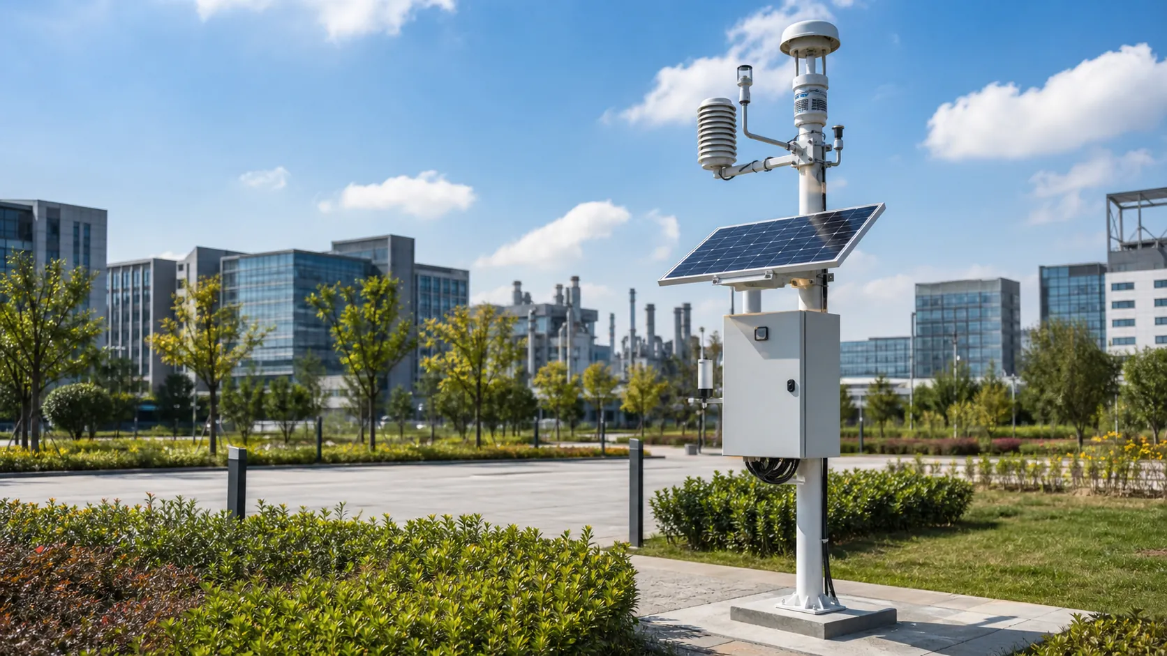
Environmental Monitoring
Deploy environmental monitoring stations with sensors, solar power, gateways, dashboards, alarms and data integration for city and industrial sites.
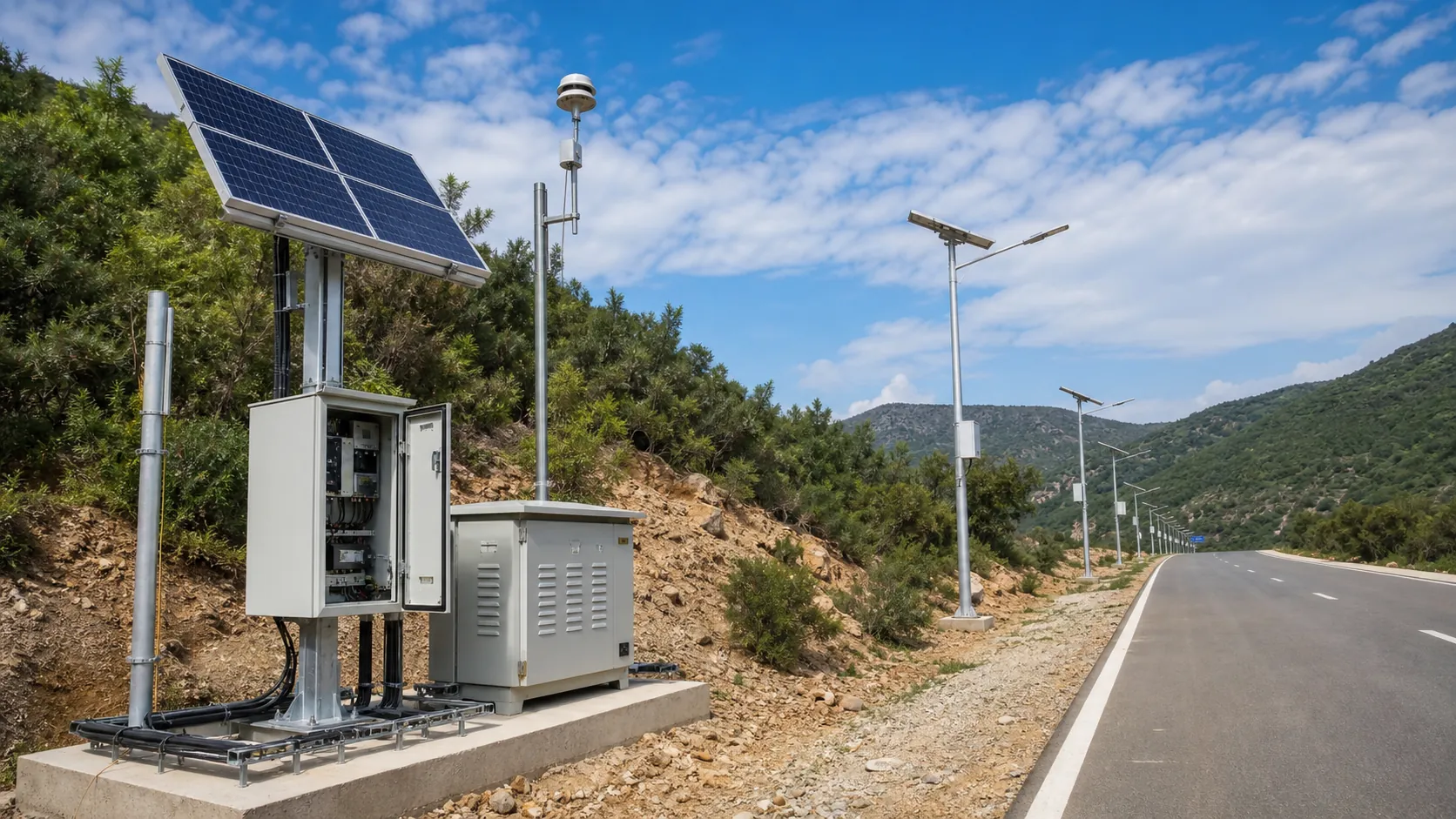
Power and Connectivity
How to choose power, battery, solar, NB-IoT, LTE, LoRaWAN, gateways and monitoring strategy for outdoor IoT infrastructure.
Ports and Logistics
Outdoor IoT infrastructure for ports, yards and logistics areas: lighting, guidance, safety, solar power, monitoring and maintenance visibility.
Frequently Asked Questions
What is the difference between a pressure transient monitor and a normal pressure logger?
A normal logger may retain readings only every few seconds or minutes, so a short pressure excursion can fall between stored samples. The RC-PTM-600 continuously acquires 100, 250 or 1,000 samples per second per channel and retains waveform windows around configured events. Its purpose is to show event timing and shape alongside normal pressure trends.
Can this station stop water hammer or automatically protect a pipeline?
The station records pressure behavior and provides supervisory alarms for engineering investigation. Reducing water hammer requires appropriate hydraulic measures, which may include revised pump or valve operation and correctly selected surge-control equipment. It does not replace a surge assessment, pressure-relief device or independently engineered protection system.
Does a 1,000-sample/s setting guarantee that every pressure spike will be measured?
No. The transmitter, process tapping, fluid conditions, filter settings and acquisition electronics together determine the effective measurement response. The fastest configuration specifies a transmitter settling time of 1 ms or less, but very short events can still be attenuated, and pressures beyond the selected range will clip.
Can it detect negative pressure in an irrigation main?
Yes, with a compound-range sensor such as -1 to +15 bar or -1 to +24 bar gauge. These ranges measure relative to local atmospheric pressure, while vapor formation depends on absolute pressure and liquid temperature. The station records pressure excursions but does not independently confirm cavitation, air ingress or contamination.
Will recording continue if the internet or mains supply fails?
A communications outage does not stop local acquisition while power remains available; event files queue for later transfer. The standard station has no internal backup battery, so recording stops when its AC supply is lost. Sites requiring pump-trip records through a complete blackout should provide an independently backed instrumentation circuit.
Can an existing SCADA pressure transmitter be reused?
It may be reused after checking its range, documented response time, damping, electrical loading and access to the signal. A slow transmitter cannot provide fast transient information simply because the recorder samples more often. Do not parallel a current-loop input without checking the loop design; a qualified signal-isolation arrangement or a dedicated sensor may be required.
How are pressure accuracy and certification confirmed before delivery?
The proposed calibrated-channel target is ±0.6% of span at +15 to +25 °C, with temperature effects assessed separately. The acceptance plan should cover static calibration, representative dynamic response and the installed pressure connection. Requested ingress, EMC, electrical-safety and radio documentation must match the ordered assembly; references to standards are not proof of existing certification.